10
\$\begingroup\$

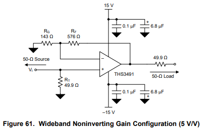
I am trying to build non-inverting amplifier with certain op amp; THS3491

The datasheet is linked below.

http://www.ti.com/lit/ds/symlink/ths3491.pdf

On page 25, there is non-inverting configuration diagram.

enter image description here

And on page 35, there is guideline for decoupling capacitors

enter image description here

It says "Use larger tantalum decoupling capacitors (with a value of 6.8uF or more) that are effective at lower freqeuncies..."

I had such bad experience with tantalum capacitors, so I wanted to avoid using these.

Is it okay to replace tantalum capacitors with ceramic ones?

Searching over the StackExchange, I found several pages with similar problem;

Tantalum capacitors vs. ceramic capacitors

MLCC vs Tantalum: For Decoupling, input to regulator and ripple reduction

The answer was that it is okay to use ceramic, but not so sure because I am dealing with Op Amps. I searched more;

http://www.dataweek.co.za/news.aspx?pklnewsid=27008

In above website, they recommend to use ceramic over tantalum, since ceramic capacitors have more advantages over tantalum.

But, is it okay to replace tantalum with ceramic capacitors?

\$\endgroup\$
4
  • 3
    \$\begingroup\$ For decoupling capacitors, yes as long as you can find similar sizes (which you may not which was probably the reason for tantalums in the first place). For capacitors in the signal path, you need to be more careful since most ceramic dielectrics suffer from piezo effects (vibrations and such will generate voltages that appears as noise), DC bias effects (reduced capacitance as the DC bias across the capacitor increases), and temperature effects. C0G/NP0 ceramic is normally used in this case because it is one of the few ceramics that do not suffer form any of these effects. \$\endgroup\$
    – DKNguyen
    Commented Mar 7, 2019 at 22:33
  • \$\begingroup\$ It's probably an older datasheet. 20 years ago tantalums were the low-ESR solution for \$C \ge 1\mu\mathrm{F}\$. We use ceramics today. \$\endgroup\$
    – TimWescott
    Commented Mar 8, 2019 at 0:28
  • \$\begingroup\$ OOI and possibly OT, what bad experiences have you had with tantalum caps? \$\endgroup\$
    – james
    Commented Mar 8, 2019 at 10:24
  • \$\begingroup\$ Tantalum's still have their place, even with the advent of polymer electrolytic and the high C/V MLCCs. Mostly on cost when you're in the few hundreds of uF and 'between' ceramic and (small can, high performance) electrolytic. We derate tantalum by 50% on voltage and have had no pyrotechnic tant failures after doing that. \$\endgroup\$
    – Cursorkeys
    Commented Mar 8, 2019 at 12:34

2 Answers 2

19
\$\begingroup\$

In most circuits, yes. And in your circuit this would be fine.

Capacitance is just capacitance and ceramic MLCCs capacitance values have increased quite a bit in the last few decades, leading to a much wider applicability (and the ongoing production shortage).

But you must be aware of a couple of caveats that are mostly exclusive to ceramics:

  • In some circuits capacitive ESR is a needed part of the circuit, a minimum value is expected and ceramics tend to have extremely low ESR. In some cases this can lead to instability and oscillations. Of particular concern would be the input of switching DC-DC converters and long DC supply cables that can be connected live.

  • MLCCs tend to have very strong voltage dependencies. These can lose 60% or more of their capacitance value under DC bias. In addition to the capacitive loss, this is a non-linear behavior that can be of concern in some circuits.

  • MLCCs ceramics are piezoelectric. Any vibration or temperature gradients can cause noise to be injected into the circuit. And, in some switching applications, you will actually hear the buzzing in the capacitors which can lead to mechanical failures.

\$\endgroup\$
2
  • 5
    \$\begingroup\$ One of the most important aspects of piezoelectric properties is the audible noise which can be quite disturbing if the working frequency of a large cap is in the audible range. \$\endgroup\$ Commented Mar 8, 2019 at 11:26
  • \$\begingroup\$ Thank you, I will check ESR and see if it is in reasonable range. \$\endgroup\$
    – user65452
    Commented Mar 8, 2019 at 14:21
8
\$\begingroup\$

Yes, it is fine from the point-of-view of the op-amps. Be careful about the voltage coefficient of the capacitors, you may need 10uF or 20uF nominal capacitance to get 6.8uF at the 15V bias voltage (they have a large voltage coefficient). (as an aside, that's a bit of a beast of a GHz range CFA so the smaller ceramic capacitors (100nF + 100pF) are really important in this particular application, see Peter Smith's comment about using reverse geometry caps for the lower capacitances - they have terminals along the long sides of the chip so less parasitic series impedance).

For example, here is a 25V 10uF 1210 capacitor that is typically down about -35% at 15V bias. Smaller capacitors will likely be worse.

From a system point of view, having a number of very low ESR capacitors bypassing the supplies could cause stability problems with your power supply regulation. If it's a lab supply or 7815/7915 linear regulators it won't be an issue (at least with the 7815), but with LDO linear regulators or negative regulators it might cause issues.

\$\endgroup\$
2
  • 1
    \$\begingroup\$ Browse here, paying attention to rated capacitance, rated voltage, and packaging to get feel for how things are affected (yes, packaging affects capacitance drop with DC bias): ds.murata.co.jp/simsurfing/mlcc.html?lcid=en-us \$\endgroup\$
    – DKNguyen
    Commented Mar 7, 2019 at 22:43
  • 3
    \$\begingroup\$ The OP may want to use reverse geometry devices for the high frequency decouplers to help minimise inductance. (0306 or 0508 perhaps) \$\endgroup\$ Commented Mar 8, 2019 at 8:49

Your Answer

By clicking “Post Your Answer”, you agree to our terms of service and acknowledge you have read our privacy policy.

Not the answer you're looking for? Browse other questions tagged or ask your own question.