2
\$\begingroup\$

I'm trying to find a way of building a new power supply for my workshop, in order to keep it small and not so hot I will be using a spare xformer to step down mains to 24v and then a variable buck converter to adjust it (and CC mode, displays and blinky stuff).

I thought it would be a good idea to use a linear regulator on the output stage to smooth things out, but I can't seem to think of a control scheme that allows me to change the voltage using only one potentiometer. The buck stage is this topology but with a external PNP transistor.(It has already been prototyped, it works alright, I know the mc34063A is old) MC34063 step down converter
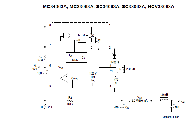
The only idea I got that ""works"" is using the buck converter output as a reference for a linear regulator (IC or discrete parts), but using a SMPS output as reference for anything is a bad idea, due to the amount of noise and fluctuations.

Linear regulator output This is the sort of output stage I can and have built (or bought) over time. Just a big discrete regulator.

In short: How to control a MC34063A step down (buck) converter so it follows the output stage +1-3 V of headroom.

\$\endgroup\$
1
  • \$\begingroup\$ Look at the datasheet for the LT3045-1. It has this feature and should give you some ideas. \$\endgroup\$
    – DKNguyen
    Commented Mar 25, 2019 at 1:35

2 Answers 2

8
\$\begingroup\$

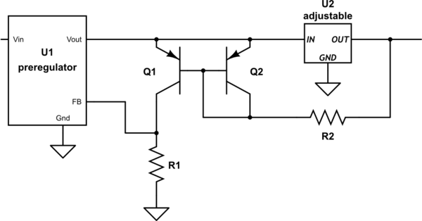
You have a "floating" voltage (the delta across your post-regulator) that you want to convert into a ground-referenced voltage to use as feedback for your pre-regulator.

One way to do this is using a current mirror.

schematic

simulate this circuit – Schematic created using CircuitLab

The general idea is that whatever voltage you have from IN to OUT on U2 will cause a certain amount of current to flow through Q2. Q1 will create a copy of this same current, and if R1 has the same value as R2, you'll get the same voltage drop across it.

If U1 is designed to hold its FB pin at, say, 1.25 V, then its output will rise until it is 1.25 V plus Q2's VBE above U2's OUT voltage. For best results, Q1 and Q2 should be a matched pair in a common package.

\$\endgroup\$
1
  • \$\begingroup\$ Is there any alternative way of implementing this by keeping the upper feedback resistor constant and changing the lower resistor? In my SMPS upper feedback resistor participates in the compensation network and phase margin suffers at certain loading conditions while following your approach. Any help will be appreciated. \$\endgroup\$
    – tinkerer
    Commented Dec 26, 2021 at 14:41
1
\$\begingroup\$

When I designed a supply like this thirty years ago I used a PNP darlington as an emitter follower with the base connected to the supply output. The emitter then provided the reference for the preregulator. A small resistor in the collector set the current limit, which would increase as the output voltage decreased as there would be more voltage on the emitter resistor.

\$\endgroup\$

Your Answer

By clicking “Post Your Answer”, you agree to our terms of service and acknowledge you have read our privacy policy.

Not the answer you're looking for? Browse other questions tagged or ask your own question.