0
\$\begingroup\$

So I watched this extremely fundamental video about voltage measurement and how it's measured. The one thing that confuses me is what people use a reference for zero potential.

The two diagrams shown below have the exact configuration and order of batteries. The values don't change either. But I get two different values of net voltage based on where I assume the zero potential to be and this assumption is arbitrary. So if I choose the zero potential to be in the middle and if my friend chooses it to be at the end, we get two different voltages and we would both be right. So what does one do to avoid such ambiguity? Is there some pre set standard on how to measure voltage? And what does a manufacturer mean when he says a supply gives a 12V or 15V output? What would the manufacturer have used as a reference? For if I change the reference point, my voltage reading for the same supply would be different and this would have consequences, right?enter image description here
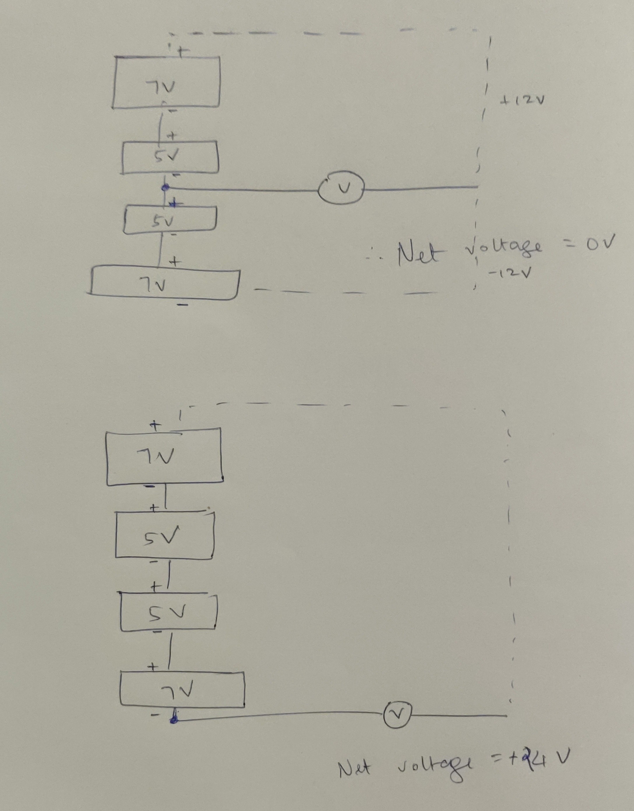
Edit: So what I'm doing in the first diagram is, I first connect the red lead at the top to measure 12V. I then connect the red lead to the bottom to measure -12V, getting a net voltage of 0v.

\$\endgroup\$
11
  • 1
    \$\begingroup\$ 1) Your diagrams don'tt show the + and - labels for the batteries. add them. 2) In the first diagram I don't get waht the dashed lines mean. You can't meaningfully connect the V meter to both the -12V and the +12V sides. \$\endgroup\$ Commented Apr 4, 2019 at 17:59
  • \$\begingroup\$ So what I'm doing is, I first connect the red lead at the top to measure 12V. O then connect the red lead to the bottom to measure -12V, getting a net voltage of 0v. \$\endgroup\$
    – penguin99
    Commented Apr 4, 2019 at 18:01
  • 1
    \$\begingroup\$ Why do you say that there is a "net voltage" of 0? You measured +12 V from point a to point b. and -12 V from point a to point c. That implies voltage from point c to point b will be 24 V, not 0 V. \$\endgroup\$
    – The Photon
    Commented Apr 4, 2019 at 18:03
  • 1
    \$\begingroup\$ No, you need to subtract. The voltage between B and C (\$V_{BC}\$) is \$V_{BC} = V_B-V_C = (V_B-V_A)-(V_C-V_A)\$. \$\endgroup\$
    – The Photon
    Commented Apr 4, 2019 at 18:09
  • 1
    \$\begingroup\$ For comparison, if Los Angeles is at +93 m relative to sea level and Death Valley is -86 m relative to sea level, that means LA is 179 m above Death Valley, not 9 m above Death Valley. \$\endgroup\$
    – The Photon
    Commented Apr 4, 2019 at 18:14

3 Answers 3

1
\$\begingroup\$

So what does one do to avoid such ambiguity?

  1. You can include a reference ("ground") symbol in your schematic. Then when you say you measure v volts at some node "A", we know what you really mean is that the voltage between "A" and the reference node is v.

  2. You can clearly say which nodes you measured the voltage between. For example, "I measured v volts between nodes 'A' and 'B'" (but now you'll have to be careful to communicate whether you mean 'A' was v volts above 'B' or vice versa).

And what does a manufacturer mean when he says a supply gives a 12V or 15V output?

They mean there will be 12 or 15 V between the two output terminals, or between one output terminal and a designated ground/reference/return terminal.

For if I change the reference point, my voltage reading for the same supply would be different and this would have consequences, right?

Yes, but if you're buying a power supply it's usually pretty clear which terminal is the reference terminal.

\$\endgroup\$
1
\$\begingroup\$

There is no zero volts. Every voltage is referenced from some point and to some point. So to remove ambiguity, you say "the voltage from the battery negative to the battery positive is ...".

Some things are implied -- a 5V power supply is presumed to have + and - terminals, and you assume that you'll read 5V from the - terminal to the + terminal. Ditto batteries. If you have a schematic that's got one ground that's clearly marked, then it's assumed that "3.3V" means "3.3V from ground". But if you have a schematic that has more than one ground (i.e., a "noisy" ground and a "quiet" ground), then those two grounds may have voltage between them, so you have to be careful about what ground other signals may be referenced to.

\$\endgroup\$
1
  • \$\begingroup\$ A physicist friend once told me that if you could separate a proton and an electron by an infinite distance then the energy of the electron would be zero volts. I suppose that could be true but ultimately not very helpful. I stopped asking my friend such questions. \$\endgroup\$ Commented Apr 4, 2019 at 18:45
1
\$\begingroup\$

When surveying the land a surveyor has to pick a reference height which is his 'zero' or datum. The height of every other point is measured above or below that. She can, if it suits, use sea level as the standard reference.

In an electrical circuit we pick some point as being zero or ground. Usually it's the battery negative (as on a car electrical system) but it can be the positive (famously on the old 6 V VW beetle) and in some cases we need a split-rail power supply and we can call the centre one 'zero' and have a '+' and '-' with respect to that.

Finally, if the circuit common is connected to earth (as in The Earth) we take that as a real zero volts, in much the same way as the surveyor might use sea-level as an absolute reference.

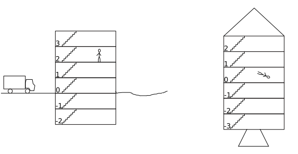
Building rocket

Figure 1. The building on the ground and shot off into space. In the space situation (electrically isolated) we can call any floor the 'ground' floor. [Image by @Transistor.]

In Figure 1 we have called the ground floor 0 (as is European practice). Floors above are numbered 1, 2, 3, ... and floors below, -1, -2. We can now calculate the number of flights of stairs to climb by subtracting the start from the end. So to travel from -1 to +3 we need to climb 3 - -1 = 3 + 1 = 4 flights.

Note that we could pick any floor as "ground". It doesn't matter - it's just a reference.

It's the same with voltages.

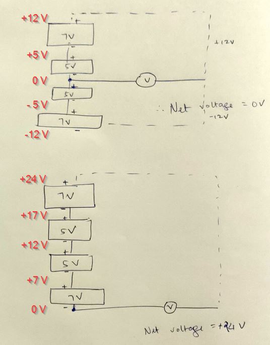
enter image description here

Figure 2. In the upper image the ground reference is mid-way up the battery stack. In the lower image the reference is at the bottom of the stack.

In both cases it's 24 V from the bottom to the top.

\$\endgroup\$

Your Answer

By clicking “Post Your Answer”, you agree to our terms of service and acknowledge you have read our privacy policy.

Not the answer you're looking for? Browse other questions tagged or ask your own question.