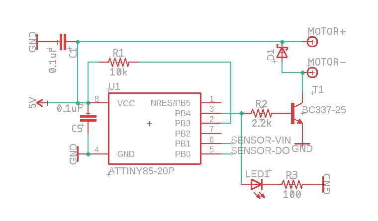
0
\$\begingroup\$

I'm trying to run a motor through an L293D turned on and off by an Attiny85. The Attiny85 has the micronucleus bootloader on it, which is why pin 3 is connected to a pull up resistor.

On the Attiny is a program that toggles PB0 on and off every second. I've attached an LED indicator on it, and while the motor is not connected to 1Y, it runs fine. It also works fine if I put an LED between 1Y and ground. But when I put a small motor between 1Y and ground, LED1 flashes briefly and then the Attiny resets.

Basically, how do I get it to not crash when running a motor through it?
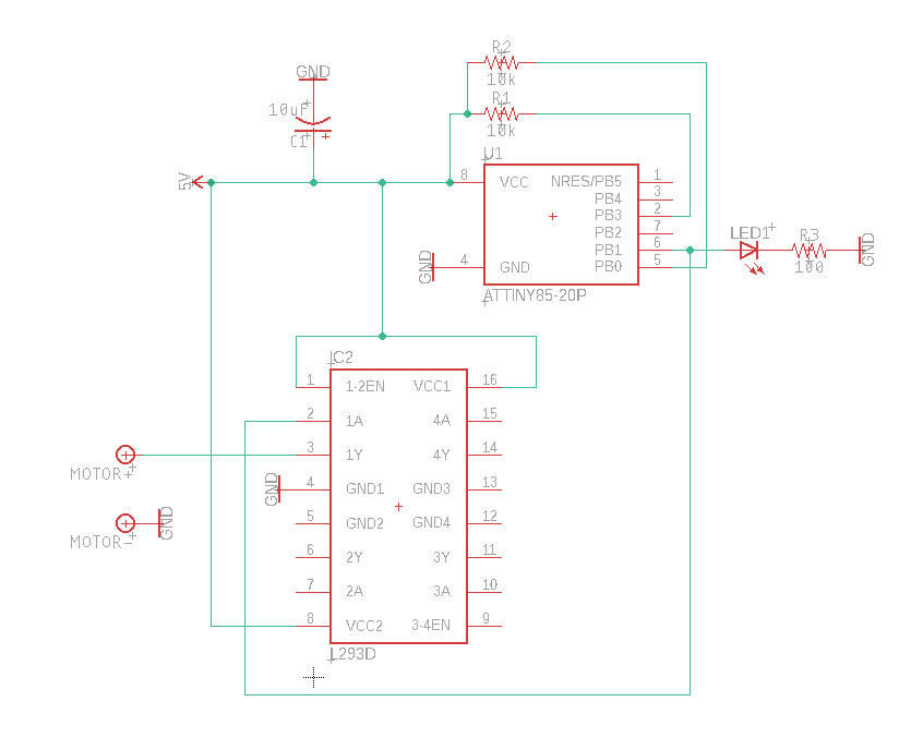
Motor on L293D I also tried the following, putting the motor directly on the power supply, doing so prevents the Attiny from starting at all.

Motor on power supply Specs:

  • 5V wall power supply with up to 3000mA output.
  • Motor pulls around 300 mA while active.
  • Also tried powering it through my computer's USB and got the same results.

What I've tried:

  • Replacing C2 with a 1000uF capacitor. That allowed me to plug the motor directly to the power supply with the Attiny85 running.
  • Putting the 1000uF capacitor between 1Y and gnd. No change.

Update 1:

The reason I was using L293D is because I didn't have any viable diodes at hand while testing. The only ones I had were too big to put on my breadboard. Connected it through alligator clips for now, and made the following changes, and that seems to be working quite well for now:

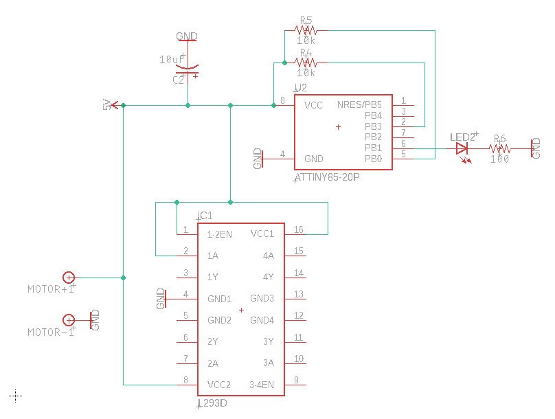
enter image description here

\$\endgroup\$
8
  • 1
    \$\begingroup\$ You have no decoupling capacitors. \$\endgroup\$
    – DKNguyen
    Commented Apr 8, 2019 at 20:11
  • \$\begingroup\$ @Toor where do I put those? \$\endgroup\$ Commented Apr 8, 2019 at 20:11
  • 1
    \$\begingroup\$ Rule of thumb is 0.1uF ceramic across every pair of power pins for every IC as close as possible to the IC. You also have no flyback diodes. \$\endgroup\$
    – DKNguyen
    Commented Apr 8, 2019 at 20:13
  • \$\begingroup\$ On top of what @Toor said, your layout matters in this regard. Please show your layout. \$\endgroup\$
    – winny
    Commented Apr 8, 2019 at 20:13
  • 1
    \$\begingroup\$ Your ultimate problem here is that your power supply is underspecified for the load. However, using the L293 the way you are makes no sense - first, it's a horribly lossy device, and a second, you don't need that to achieve the unidirectional control you have wired for. What you want is a good power supply, and a good low threshold N-FET wired as a low side switch. \$\endgroup\$ Commented Apr 8, 2019 at 21:15

1 Answer 1

2
\$\begingroup\$

You have no decoupling capacitors.

You need decoupling capacitors because whenever the ICs switch they will try to draw a surge of current. The power supply can't respond fast enough and even if it does, the current surge will produce a voltage drop through the parasitic inductance of the wires and traces. Either scenario will cause a brownout.

The rule of thumb is to place 0.1uF ceramic capacitors across every pair of power pins as close to the IC as possible.

\$\endgroup\$
12
  • 1
    \$\begingroup\$ No. While that is a good idea as a general principle, it is not the issue here. The issue is that the motor is overloading the power supply, whatever that is. If this "solves" the problem it's luck, not sound engineering. \$\endgroup\$ Commented Apr 8, 2019 at 21:11
  • \$\begingroup\$ Motors draw much more than steady state when starting. Again, bypass capacitors are a good idea. But they are not a sound solution to this problem. \$\endgroup\$ Commented Apr 8, 2019 at 21:14
  • 1
    \$\begingroup\$ OP has stated that they already added 1000uF caps prior to adding this post which should have alleviated current surge issues from the motor. \$\endgroup\$
    – DKNguyen
    Commented Apr 8, 2019 at 21:15
  • 1
    \$\begingroup\$ Read their actual statement and you'll see that they put that cap in an utterly useless place. \$\endgroup\$ Commented Apr 8, 2019 at 21:16
  • 1
    \$\begingroup\$ As I just mentioned larger capacitors don't work at higher frequencies where the effect of parasitic inductances are most prominent. This inductance is why you have to place the smaller capacitors close to the chips. In other words, with larger capacitors, you don't need to worry about as much with physical placement and closeness. So just one 1000uF for everything should be enough. \$\endgroup\$
    – DKNguyen
    Commented Apr 9, 2019 at 21:25

Your Answer

By clicking “Post Your Answer”, you agree to our terms of service and acknowledge you have read our privacy policy.

Not the answer you're looking for? Browse other questions tagged or ask your own question.