1
\$\begingroup\$

I have an ATtiny85 switching an NPN transistor, which will in turn switch on a relay that will run a motor. Everything is run off a 3.7V 18650 Li-Ion battery, but I have since moved over to a variable power supply with same problem:
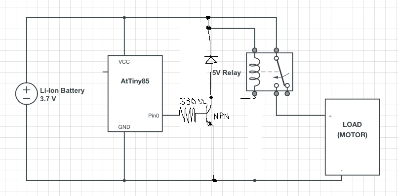
some sort of description

Without the motor, the relay switches fine, ATtiny85 will switch the relay on for one second, and then off for one second, and repeat, and the oscilloscope (connected to relay output and GND) and clicks are showing correct behaviour for the relay.

When I connect the motor, the relay still clicks, but the oscilloscope is showing zero voltage. Seems like relay tries to switch, but doesn't. I connected an LED to Pin0 of the ATtiny85, and it flashes instead of staying on for one second and going off for 2 second.

Seems to me that the problem could be:

  1. The ATtiny85 is resetting because not enough current going through. This doesn't make sense because I've switched over to a bench power supply and same thing happens, voltage is still the same.
  2. Some sort of feedback from the motor? The motor runs fine if I connect it directly to battery so I don't think power is an issue.

Some additional information:

  • Relay switches on for 1 second then off for 1 second. I am not doing PWM, but just have this on/off behaviour for testing.
  • This is the motor: 3V-12V water pump motor
  • Power supply is set at 3.9V with 2A current available. Increasing it to something like 5V still doesn't work.

EDIT: Although the answers all helped me figure out my problem, I chose the one that helped me the most. Found that it wasn't back-emf or your standard type of decoupling required. The motor was dropping the voltage down hard and no capacitor was going to fix it (already had these in place), although these are common issues.

More findings here

\$\endgroup\$
7
  • \$\begingroup\$ What kind of motor is this? Do you have a part number? And what frequency is the duty cycle? Is the bench power setup EXACTLY the same as the battery setup? I'm pretty sure the start up surge in the motor is dropping the voltage out from under the ATTiny and forcing it to restart. Also, could be simply dropping out the relay. \$\endgroup\$
    – user39962
    Feb 16, 2015 at 23:29
  • \$\begingroup\$ Hey, I added the information you wanted in question description. Thanks. \$\endgroup\$
    – PGT
    Feb 17, 2015 at 0:15
  • \$\begingroup\$ Where is the decoupling and bulk capacitance? \$\endgroup\$ Feb 17, 2015 at 0:53
  • \$\begingroup\$ I have a diode across the motor, and caps across VCC/GND of ATtiny85 as well as across the motor. \$\endgroup\$
    – PGT
    Feb 17, 2015 at 16:12
  • \$\begingroup\$ Why are you trying to drive a 5V relay coil with less than 3.7V? Guessing there's about 100mV across the CE of the transistor at saturation. \$\endgroup\$
    – lyndon
    Feb 17, 2015 at 19:15

3 Answers 3

2
\$\begingroup\$

I have two suggestions for you:

1) check to make sure that the relay is able to handle the current the DC motor is pulling.

2) use the variable power supply to run the control circuit, and the battery to run the motor with relay. if this proves to be working, you can then work your way back to re-integrate the motor back to your system.

\$\endgroup\$
1
  • \$\begingroup\$ You're right, it works if I isolate the motor+output of relay from the control circuit+switch of relay. Not sure if it's back emf killing it, or if it's eating up all the current. My power supply can supply up to 2A, and I don't see the current go up at all when it switches on. \$\endgroup\$
    – PGT
    Feb 18, 2015 at 2:56
1
\$\begingroup\$

Depending on how the motor is wound, it could be giving an inductive kick onto the power supply rails as the brushes disconnect from the coils. This is why you see sparks at the brushes of a spinning motor. This kick could glitch the chip and cause exactly the kind of stuff you are seeing (relaTo remedy this, you can try putting another flyback diode across the motor leads just like the one across the relay coil.

It is also good practice to use a decoupling capacitor across the leads of the chips. This will filter any sudden power spikes or dips that could otherwise cause the chip to glitch. Try putting a ~1uF capacitor physically as close to the leads of the chip as possible.

\$\endgroup\$
4
  • \$\begingroup\$ Thanks for the tips. When you say leads of the chip, you mean VCC and GND? \$\endgroup\$
    – PGT
    Feb 17, 2015 at 4:14
  • \$\begingroup\$ Just tried with diode across motor (cathode to +ve of motor) and a 100uF cap (+ve to VCC, and -ve to GND of ATtiny85), still same issue. Totally assuming 100uF should be fine here. \$\endgroup\$
    – PGT
    Feb 17, 2015 at 4:24
  • \$\begingroup\$ Try a smaller capacitor if you have it, bigger is not always better for filtering (google decoupling capacitor ESR). Maybe 1st try powering (just) the AVR directly from a couple of AA batteries, just to make sure that this is a power supply problem and not something else entirely. So you would disconnect the Vcc of the chip from the above circuit completely and instead connect to the + side of a pair of AA batteries in series, then connect the - side of the battery stack to the ground in your circuit. \$\endgroup\$
    – bigjosh
    Feb 17, 2015 at 15:52
  • \$\begingroup\$ Yeah it's the same behaviour on battery; everything works fine until I connect the motor. Tried with a 100nF ceramic cap, same thing. I don't have anything in between and might have to start connecting my larger caps in series to get 10uF. \$\endgroup\$
    – PGT
    Feb 17, 2015 at 16:10
0
\$\begingroup\$

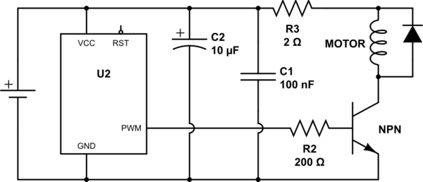
Something like this:

schematic

simulate this circuit – Schematic created using CircuitLab

Are you actually PWM'ing?
Why relay?
Why not FET?

\$\endgroup\$
3
  • 1
    \$\begingroup\$ share EDIT flag \$\endgroup\$
    – Jon
    Feb 17, 2015 at 6:53
  • \$\begingroup\$ I am not PWMing, I'm just switching the motor on and off every second because I'm too lazy to press a button. My BJTs can't handle more than 500mA, the motor will pull about 1.4A, and sometimes spike to 2A depending on start/stop or load. I don't have any FETs, so can't use them. \$\endgroup\$
    – PGT
    Feb 17, 2015 at 16:14
  • \$\begingroup\$ I recommend 1.6<R3<2 and using a FET: <1$ sparkfun.com/products/10213. The motor will consume all available current if it's allowed to. \$\endgroup\$
    – Jon
    Feb 17, 2015 at 19:31

Your Answer

By clicking “Post Your Answer”, you agree to our terms of service and acknowledge you have read our privacy policy.

Not the answer you're looking for? Browse other questions tagged or ask your own question.