0
\$\begingroup\$

What is the purpose of putting attenuation circuit before op-amp input? I cant find the actual reason for this topology. Is there any reason behind it? Why we need to attenuate the incoming signal but at the end we amplify it.

Signal input -> attenuation circuit (reduce incoming signal level) -> op amp input (amplify signal level)


sorry for late response.

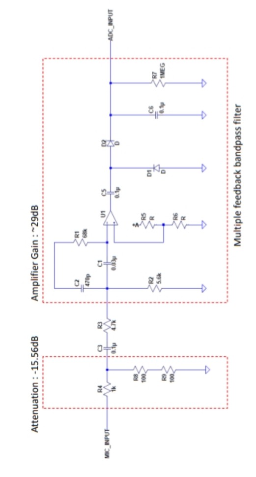
I attached my circuit diagram. Basically it just a simple voltage source (from MIC) + bandpass filter with positive rectifier (range within 5KHz bandwidth) and this signal will input to ADC for detection.

Based on circuit below, I confirmed the attenuation and gain

Attenuation level : -15.56dB Gain level : 29dB

If based on above level, can we just set gain of the amplifier to be 13.44dB (gain level - attenuation level)?

I'm thinking to reduce the component used by deleting the attenuation circuit before the amplifier input.

enter image description here

.

\$\endgroup\$
4
  • 3
    \$\begingroup\$ Show an actual published schematic for this, because it likely depends on context. \$\endgroup\$
    – pipe
    Commented Apr 14, 2019 at 9:45
  • 1
    \$\begingroup\$ This clearly depends on context - besides the answers already provided at this point I an think of opamps input limitations such as common mode, rail-to-rail limitations, filtering, input protection, flexibility to adjust the input range by changing the divider values, etc. \$\endgroup\$
    – le_top
    Commented Apr 14, 2019 at 12:02
  • \$\begingroup\$ That filter looks broken to me, no actual feedback! Maybe R1 should go to the output? Also, what about the opamp input bias and offset currents? \$\endgroup\$
    – Dan Mills
    Commented Apr 15, 2019 at 12:15
  • \$\begingroup\$ You're correct, the schematic have some mistake. In actual circuit, resistor R1 is connected to the output as a feedback. \$\endgroup\$
    – user218385
    Commented Apr 15, 2019 at 13:02

2 Answers 2

2
\$\begingroup\$

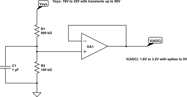
In addition to Bimpelrekkie's answer, here is another very common scenario:

schematic

simulate this circuit – Schematic created using CircuitLab

Here we are monitoring a system power rail (typical in avionics). As most ADCs have reference voltages of 5V (or less) we need to change the effective range of the supply rail being monitored.

We don't want to waste power so I am using high value resistors, but the source resistance to an ADC typically needs to be quite low (a few k ohms at most usually), so the sense point in the voltage divider is buffered to properly drive such an ADC.

I haven't taken the trouble here to convert the signal to a 0V to Vref span and in fact it is rarely necessary in such a situation.

\$\endgroup\$
3
  • \$\begingroup\$ Sorry but i can't see the relationship with the attenuation circuit. From my understanding, we'll only use buffer amp if the input source resistance is high (buffer amp purpose is to make lower impedance output feed into ADC input). \$\endgroup\$
    – user218385
    Commented Apr 15, 2019 at 13:38
  • \$\begingroup\$ @user218385 And do you think voltage dividers have a low output resistance? \$\endgroup\$
    – Hearth
    Commented Apr 15, 2019 at 13:40
  • \$\begingroup\$ @Hearth, to answer that, it always depends on how you define your application. Can you agree with that? \$\endgroup\$
    – user218385
    Commented Apr 15, 2019 at 14:29
2
\$\begingroup\$

I cant find the actual reason for this topology

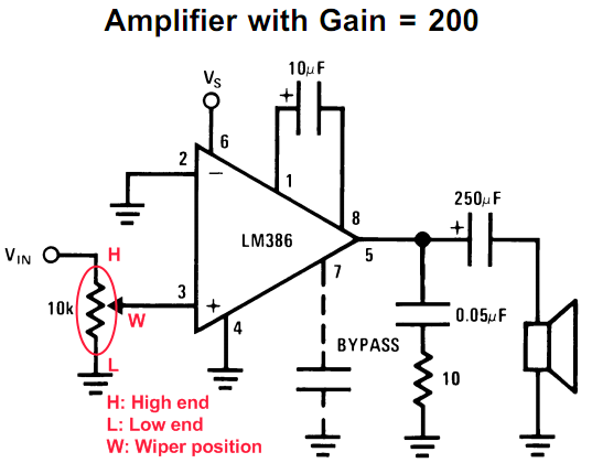
I can, here's an example:

enter image description here

This is an LM386 audio amplifier with an attenuator at its input. The attenuator is the volume control.

Since we have no idea what the input voltage from the source is this allows us to set the volume control such that the output level is where we want it to be. Within certain limits of course. Also the input voltage cannot be too small or too large.

If the volume control was not present at the input we would not be able to prevent the amplifier from saturating (clipping) when the input level is too high.

Also, since this is a power amplifier, attenuating at the output is impractical as the power level is much higher (compared to the input), attenuating the signal at the output would mean severe power loss. You first make a lot of power and then waste most of it for a low volume. So efficiency is also a good reason to do the signal attenuation before amplification.

\$\endgroup\$

Your Answer

By clicking “Post Your Answer”, you agree to our terms of service and acknowledge you have read our privacy policy.

Not the answer you're looking for? Browse other questions tagged or ask your own question.