3
\$\begingroup\$

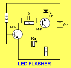
I have this circuit working on my breadboard. This circuit does exactly what I need in term of effect but so far I have not been able to find a way to get more current to the LED output. I need to be able to run either this circuit or one that does the same thing but with a 1/2 watt or 1 watt LED. I also need to be able to manage or set the strobe rate.

Is it possible or possible to use some variation on this?

=============================

EDIT/UPDATE

I tried using a couple of different Darlington transistors (the one on the breadboard now is a Fairchild Transistors Darlington PNP Epitaxial Sil US HTS:8541408000 ECCN:EAR99

No luck so far. When the BC557 PNP is replaced by the Darlington the circuit powers the LED up slowly (too slow) then it fails to shut off.. Q1 does not turn off.. Apparently for some reason the discharge of the electrolytic does not drop the voltage low enough to turn off Q1 let alone keep it off for any length of time.. I tried a few changes of resistors but no luck.. Apparently I have not fully grasped the dynamics at work in how/why Q1 shuts off and why the Darlington has changed this.

I am still new to this stuff though I have been studying up...

I need to get this circuit or a very similar one to FULLY power optionally a 1/2 watt LED or 2 half watt LEDs, so from 120ma to 240ma, depending on resistors. Edit(and power input is really 5vdc)

Thanks,

Jim

\$\endgroup\$
1
  • 1
    \$\begingroup\$ Have you measured the current (voltage drop across the 22R during the flash)? Maybe your flash is too short and you really want to lengthen it. \$\endgroup\$
    – gbarry
    Commented Oct 10, 2012 at 20:56

3 Answers 3

2
\$\begingroup\$

The current through the LED is limited by the "22R" resistor. Lowering the resistance value will increase the current and thus brightness. make sure the PNP transistor is also rated for the current. A "darlington pair" of transistors has a much higher gain and can be used for higher-current applications.

Current will be (6 - 2.0 - 0.2) / R.
- 6v supply
- 2.0v (approximate) drop across a red LED (blue may be up to 3.3v) - 0.2v drop across the collector/emitter transistor junction

The cycle time will be a function of the 10u capacitor and 22R. Lowering the capacitance and/or resistance will make it cycle faster (I think :-).

\$\endgroup\$
4
  • \$\begingroup\$ The forward voltage drop across the LED will not be 0.7V. That may be the drop for a typical silicon diode but the LED will be greater. A red LED can be 2.0 -> 2.2V, a green LED can be 2.4 -> 2.7V and white and blue LEDs are even higher. \$\endgroup\$ Commented Oct 10, 2012 at 22:10
  • \$\begingroup\$ Right, thanks. I was busy thinking about the drop across transistors and forgot about the difference in light-emitting diodes. (corrected in-line) \$\endgroup\$ Commented Oct 11, 2012 at 0:07
  • \$\begingroup\$ Changing the resistors so far has not helped. This circuit delivers first a small amount of current then the full amount to get the strobe effect. I will re examine the problem later tonight. Am I to understand that using different transistors will produce higher gain in current? The frequency of the strobe is adjusted by changing the 330R. \$\endgroup\$
    – Jim
    Commented Oct 11, 2012 at 1:07
  • \$\begingroup\$ I need to keep the effect AS IS... so whatever changes made need to scale up both the initial powering and final powering of the LED.. Perhaps both transistors need to be changed? The LED cycle ends when the amp is driven to saturation according to the specs..I am concerned this circuit will work with the changes.. I am a noob and appreciate all the help. \$\endgroup\$
    – Jim
    Commented Oct 11, 2012 at 3:34
1
\$\begingroup\$

Have you considered using a LM555 in a astable configuration driving a power FET or a transistor?

This way you can easily add variable resistors to control the frequency and the duty cycle.

\$\endgroup\$
2
  • 1
    \$\begingroup\$ 555's are EVIL. EVIL, I say! :) The cool thing about the OP's schematics is that it is very low power, much less than a typical 555. The OP is talking about needing more power into the LED so this probably isn't an issue for him, but I'm just trying to show that a 555 isn't always a good solution. \$\endgroup\$
    – user3624
    Commented Oct 10, 2012 at 21:23
  • \$\begingroup\$ Circuit mods not working please see update above. \$\endgroup\$
    – Jim
    Commented Oct 17, 2012 at 4:57
1
\$\begingroup\$

In order to drive a 1 Watt LED such as white, it needs around 330mA @ 3.3V.

The PNP will need much more current gain so choose a Darlington that can handle 500mA with 1W dissipation derated to 50%.

The drop across the Darlington will be around 1.2V when ON leaving the difference across your current limiting resistor of 1.5V. The accuracy of the 6V will affect the current. For now, 6V-3.3-1.2=1.5V > Re= 1.5V/330mA = 4.5 ohms 1W . If 6V=>6.5V we get I = 2.0V/4.5 = 440mA You can choose the nearest value of R. These estimates also depend on LED, PNP and 6V characteristics for internal series resistance at operating current. You may want a good Cap across the supply, but may not be essential.

I assumed you wanted white, but obviously this changes Re if you choose a color like Red to approx double the Re for approx half the voltage.

\$\endgroup\$

Your Answer

By clicking “Post Your Answer”, you agree to our terms of service and acknowledge you have read our privacy policy.

Not the answer you're looking for? Browse other questions tagged or ask your own question.