2
\$\begingroup\$

I am trying to create a ping pong ball sized light-up ball that should light up when held in my hand, as in the 80's toy inspired by the movie/television series "Star man".

The circuit must be powered by a coin battery cell, preferable a 1.5 V LR44.

I have a ZXSC380FHTA LED driver and a 47 μH or 100 μH RF inductor.

The LED is a standard 5 mm white LED from a broken computer fan which lights up using only the LR44 button cell, LED driver, and inductor.

I have tried with a 2N2222A transistor to drive the touch (skin) switch and even tried to create a Darlington transistor by combining two of these, but no success.

So far I only tried on a breadboard to get a skin connection using two pins. Is the surface area to the skin insufficient, or is there something wrong with the electrical design?

Does anyone have a suggestion?

When driven by 5 V from an Arduino it is no problem to light up the LED with just a transistor and using the skin to close the circuit between +5 V and transistor base, but when transitioning to 1.5 V I guess there is too little voltage to drive even an LED driver of the type mentioned above.

Also, should the load, i.e. the LED driver/inductor/LED be placed at the collector or emitter side of the transistor?

Update: When using 3 x 2n2222a in a darlington config, I can get the led to shine using a 3V coin cell. But only if the finger is licked a little before pushing the two pins I use to test this on the breadboard. I will try to use a bigger piece of metal as connector next and maybe order some triple darlington transistors to further test. Also when googling: "energy ball" seem to hit a simulcrum of what I want, the nowadays sold "energy balls" doesn't light up, but blink and make annoying noises. Which to some might seem like an improvement but to me seem like; "Oh why, for the love of a hot women (or man, if you are so inclined)."

\$\endgroup\$
4
  • \$\begingroup\$ Some of them that I've used have two small metal contacts on the outside of the ball similar to a ping-pong ball. When both were in skin contact the ball would light up. I believe they used three BJTs, not two. I've since designed a circuit that can be used for similar purposes -- was designed to detect even slightly moist surfaces -- and I may be able to find the design (or recreate it) at some time later. \$\endgroup\$ Commented Feb 1, 2023 at 17:11
  • \$\begingroup\$ As in three BJT's in a darlington configuration? \$\endgroup\$
    – Erik
    Commented Feb 1, 2023 at 18:05
  • \$\begingroup\$ Well, in my case not exactly. But in your current situation, assuming you are willing to have two contacts protrude the ball, I'd try that as a "next step." It might get you there. \$\endgroup\$ Commented Feb 1, 2023 at 18:10
  • \$\begingroup\$ you want a 3v cell (or two in series( and at least a darlington, maybe 2. basically, build a ghost detector and backoff the transistor count until you have to actually touch it to light. \$\endgroup\$
    – dandavis
    Commented Feb 1, 2023 at 23:52

2 Answers 2

1
\$\begingroup\$

Give this a try:

schematic

simulate this circuit – Schematic created using CircuitLab

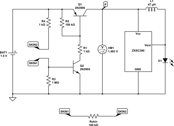
With the transistors in this configuration you will obtain a current gain very similar to a darlington pair, but the voltage at P can get very close to the full battery voltage, as shown on voltmeter VM1.

This circuit will work without R2 and R3, but you'll find that the battery will discharge more quickly, even without the LED lit. R2 and R3 keep the two transistors switched completely off when the ball is not "held", so that leakage current will be kept down in the nanoamps.

\$\endgroup\$
2
  • \$\begingroup\$ Thanks, will try, if I can source ZXSC380. \$\endgroup\$
    – Erik
    Commented Sep 23 at 6:20
  • \$\begingroup\$ Source!? Too long ago I forgot I had this, but FHTA-suffixed. I guess the depicted IC made it look bigger... \$\endgroup\$
    – Erik
    Commented Sep 23 at 6:37
0
\$\begingroup\$

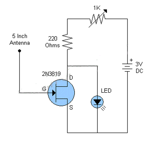
I have made one of these in the past and they are certainly sensitive. You might need some kind of ESD protection but there are lots of interesting possibilities with this

enter image description here

\$\endgroup\$
2
  • 1
    \$\begingroup\$ The 2n3819 might be better than a 2n2222a transistor for my project. But will it work as I described in my question, i e closing two metal points with the skin turn on the Drain-Source current flow? And if so should those metal points be between the gate and battery +? Will it work with a 1.5v battery and a led driver? \$\endgroup\$
    – Erik
    Commented Feb 1, 2023 at 16:29
  • 2
    \$\begingroup\$ The pictured circuit constantly drains the battery \$\endgroup\$ Commented Feb 1, 2023 at 19:05

Your Answer

By clicking “Post Your Answer”, you agree to our terms of service and acknowledge you have read our privacy policy.

Not the answer you're looking for? Browse other questions tagged or ask your own question.