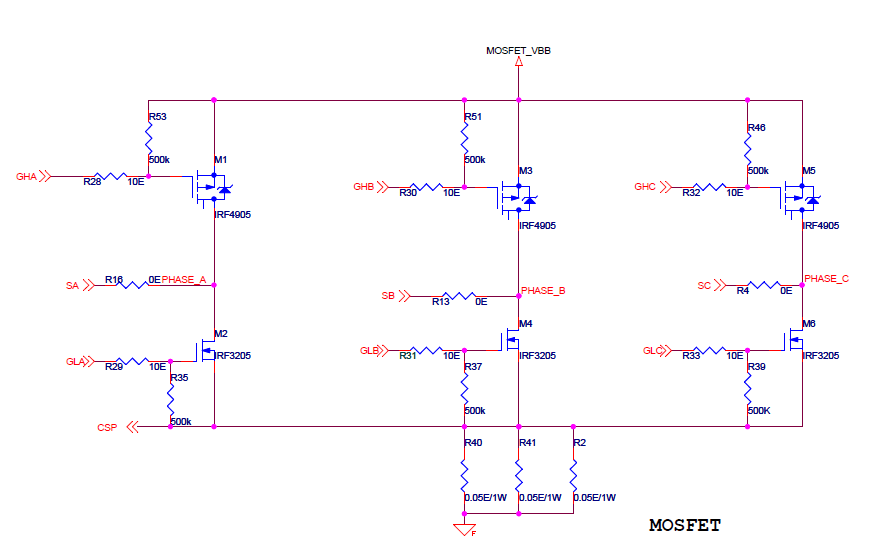
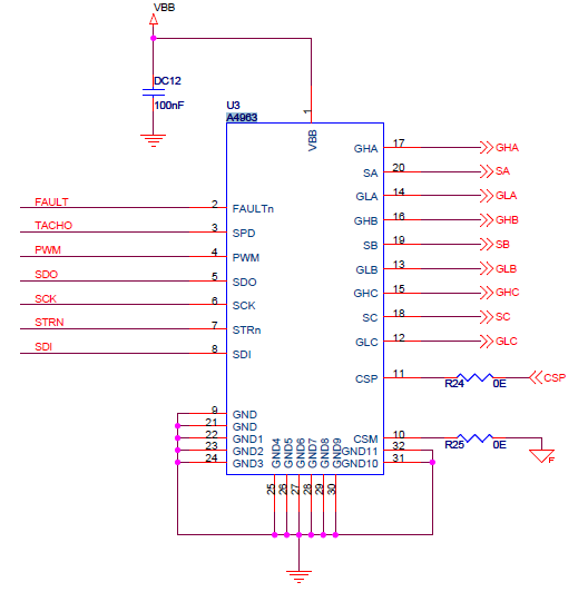
I am quite confused about choosing the correct value gate resistor. I came to know that it must be within 20-50 ohm
There is no must on this, it should be an appropriate value for your application (0R is appropriate sometimes).
The purpose of gate resistors is usually to control EMI, this happens by slowing down the turn-on and turn-off of the FET by limiting the rate of transfer of charge in and out of the gate. They also help with ringing on the gate itself; the trace connecting your driver to your FET has a small amount of inductance.
If you consider the gate as a capacitor then this should be easier to understand.
If you don't have excessive ringing on your gate (use a scope to check) then you will want the gate resistance to be as small as possible to reduce switching losses in your FETs. I generally start with 10R myself. Turn-off of the FET is usually desirable to be as fast as possible, so you can have turn-on limited by the gate resistor and a fast turn-off by placing a low Vf diode, such as a BAT17, in parallel with the resistor (anode on the gate side).
I am also confused about sensing resistor too. is is quite in range or what?
If you look on Page 24 of the datasheet it talks about the current limit. If 5.1A is your desired current limit then:
5.1A = Vilim / 0.0166R
So: Vilim = 305mV
This is outside the range of Vilim that that can be programmed (200mV).
If you remove one of the 0R05 resistors then then Vilim becomes:
5.1A = Vilim / 0.025R
So: Vilim = 204mV
Which is now (just) in-range. You will need to program the VIL register appropriately and also note that in closed-loop control the duty-cycle of your driving waveform determines the current limit.
By using P = I2R you can verify the 1W rating for your sense resistors is still appropriate.


