2
\$\begingroup\$

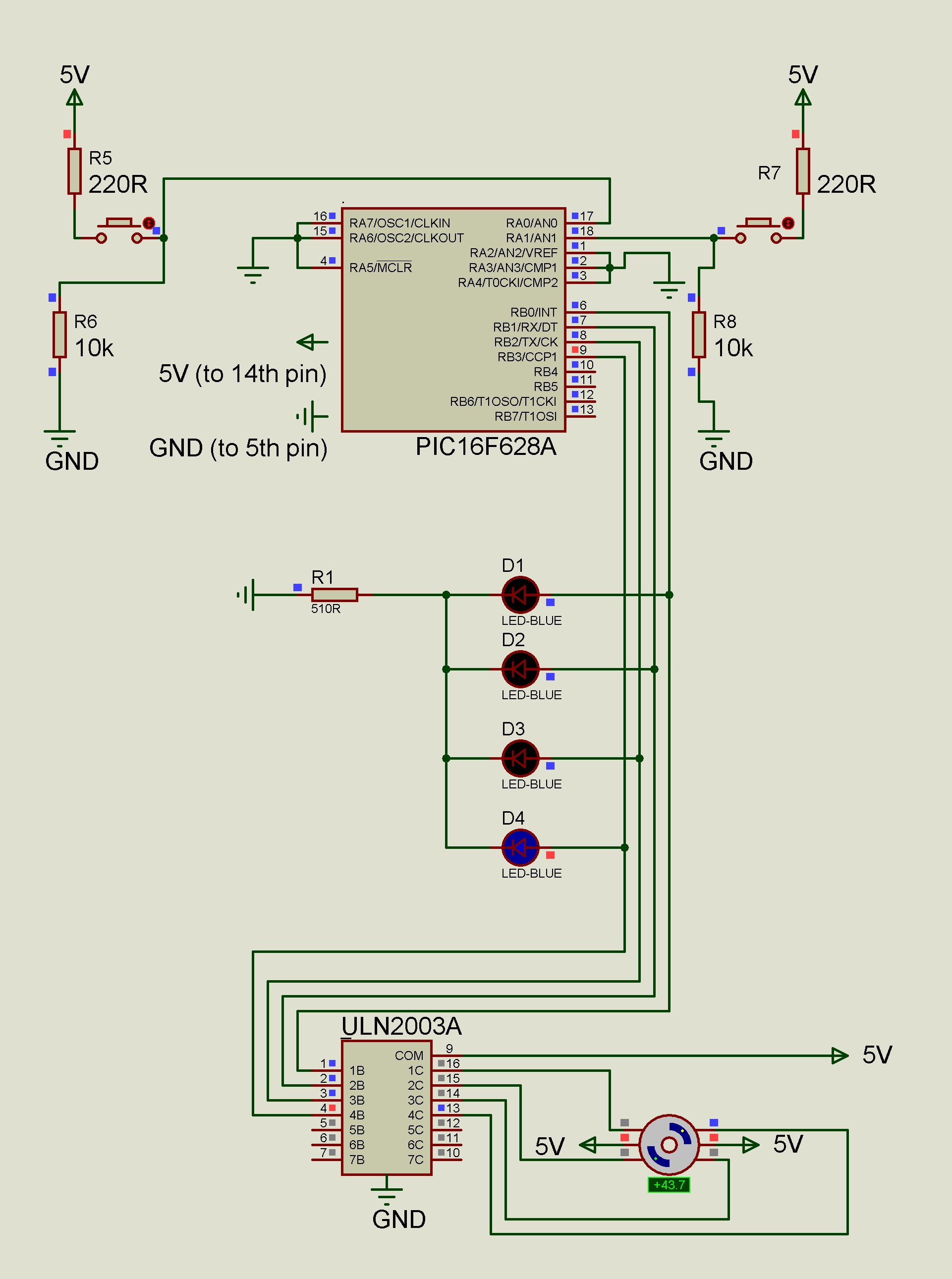
I simulated this circuit successfully in proteus but it doesn't work on breadboard.

The motor is unipolar stepper motor

I checked the motor and ULN2003A darlington transistor IC.

They work perfectly. Only problem is with the pic. I used a 16f628a

edit 1: programming device detects and programs the PIC. but when i put the PIC on the breadboard it doesnt do anything.

edit 2: programming device is "brenner 8" and software is "USburn"

edit 3: fixed circuit and codes after answers and comments

edit 4: after fixing; only 2 leds are constantly lit and nothing else happened.

edit 5: (May 10th 2019 11:15 hours GMT) it doesnt work no matter what i tried (i tried all answers to this date). Fortunately the teacher gave me a decent grade. I will try with a pickit 3 if i want to try again(currently using a brenner 8).

here is the schemetic

// CONFIG
#pragma config FOSC = INTOSCIO  // Oscillator Selection bits (INTOSC oscillator: I/O function on RA6/OSC2/CLKOUT pin, I/O function on RA7/OSC1/CLKIN)
#pragma config WDTE = OFF       // Watchdog Timer Enable bit (WDT disabled)
#pragma config PWRTE = OFF      // Power-up Timer Enable bit (PWRT disabled)
#pragma config MCLRE = OFF      // RA5/MCLR/VPP Pin Function Select bit (RA5/MCLR/VPP pin function is digital input, MCLR internally tied to VDD)
#pragma config BOREN = OFF      // Brown-out Detect Enable bit (BOD disabled)
#pragma config LVP = OFF        // Low-Voltage Programming Enable bit (RB4/PGM pin has digital I/O function, HV on MCLR must be used for programming)
#pragma config CPD = OFF        // Data EE Memory Code Protection bit (Data memory code protection off)
#pragma config CP = OFF         // Flash Program Memory Code Protection bit (Code protection off)

#include <xc.h>

void wait();

void main(void)
{
    CMCON = 7;
    TRISA = 255;
    TRISB = 0;
    PORTB = 1;
    PORTA = 0;

    int portb_value = 1;
    int minimum_step_count = 3;
    int counter = 0;

    wait();

    while(1)
    {
        if(PORTA == 1)
        {          
            while( counter < minimum_step_count )
            {
                counter++;
                if(portb_value != 16)
                    portb_value=2*portb_value;        
                if(portb_value == 16)
                    portb_value=1;
                PORTB = portb_value;    
                wait();
            }
            counter=0;
        }
        if(PORTA == 2)
        {           
            while( counter < minimum_step_count )
            {
                counter++;
                if(portb_value == 1)
                    portb_value=16;
                if(portb_value != 1)
                    portb_value=portb_value/2;
                PORTB = portb_value;     
                wait(); 
            }
            counter=0;
        }

            PORTB = 0;

    }

}

void wait()
{
    int time = 0;
    while( time < 30000 )  
    {
        time++;
    }
}
\$\endgroup\$
6
  • \$\begingroup\$ What does it do wrong? Does it burn up, explode, lay there doing nothing or get up and smoke your hamster and feed your cigarettes? \$\endgroup\$
    – JRE
    Commented May 3, 2019 at 17:06
  • \$\begingroup\$ xD it do nothing at all. programming device detects and programs the PIC. but when i put in on breadboard it doesnt do anything. \$\endgroup\$
    – hfc
    Commented May 3, 2019 at 17:09
  • 2
    \$\begingroup\$ Where are your CONFIG settings? The default (if any) of that compiler may not be what you need. \$\endgroup\$ Commented May 3, 2019 at 17:12
  • \$\begingroup\$ i just downloaded "MPLAB X IDE v5.15" for "8bit midrange PIC microcontrollers ( aka PIC 16f628a)" im using x8 compiler it is default of MPLAB. i didnt do any configurings. \$\endgroup\$
    – hfc
    Commented May 3, 2019 at 17:15
  • 2
    \$\begingroup\$ And also: You need to do something with the pins of PORTA that you are not using. Having them floating will result in undefined behavior. Tie them to GND. \$\endgroup\$
    – MartinF
    Commented May 3, 2019 at 17:22

5 Answers 5

6
\$\begingroup\$

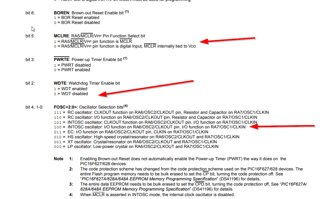
You need to set the configuration. See the datasheet 14-1.

In particular, set /MCLR to an input or tie it to Vdd with a 10K resistor and set the clock up to use the internal RC clock and disable the WDT.

enter image description here

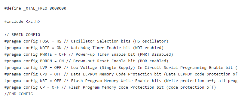
While you can typically set this in the IDE, you should insert pragma statements to set it in your code. Here is an example (not suitable for your situation) from this tutorial.

enter image description here

As mentioned in the comments, you should either tie inputs to a known voltage or enable the internal pull-up resistors (see the datasheet for details). If the /MCLR pin is enabled for use as /MCLR function and you decide to add a reset switch, be sure to follow the datasheet recommendation for a series resistor of 50-100\$\Omega\$.

\$\endgroup\$
6
  • \$\begingroup\$ your answer seems good. im configuring now. but i dont have the PIC programmer. it is in the school. ill check on monday. Also the teacher using CC5x compiler instead of x8 compiler. he doesnt configure the pic, so it seems because of cc5x. But i cant able to install cc5x its not working. \$\endgroup\$
    – hfc
    Commented May 3, 2019 at 17:53
  • \$\begingroup\$ i copied an pasted this codes to my source file \$\endgroup\$
    – hfc
    Commented May 3, 2019 at 17:57
  • \$\begingroup\$ #pragma config FOSC = INTOSCIO #pragma config WDTE = OFF #pragma config PWRTE = OFF #pragma config MCLRE = OFF #pragma config BOREN = ON #pragma config LVP = ON #pragma config CPD = OFF #pragma config CP = OFF \$\endgroup\$
    – hfc
    Commented May 3, 2019 at 17:58
  • \$\begingroup\$ i tried on monday but doesnt work :( \$\endgroup\$
    – hfc
    Commented May 6, 2019 at 11:23
  • \$\begingroup\$ did you tie MCLR to Vdd via 10K as suggested ? microchipdeveloper.com/8bit:guide microchipdeveloper.com/8bit:mclr \$\endgroup\$
    – pm101
    Commented May 8, 2019 at 10:40
3
\$\begingroup\$

Do you have the program configured to use the internal oscillator? (Page 99 of the datasheet) You should also try tying the MCLR pin to Vdd or use one of the circuits described on page 108

EDIT:

Be sure to add a 0.1uF decoupling capacitor near the power input of the microcontroller.

There are some additional problems I noticed with your code. You should increase the time for the wait() function since 30,000 ticks is going to be a short period of time. I would use an unsigned int and take it to 150,000. The other thing is that you need to change the second if statement in your while loops to an else if. Currently when portb_value == 1 then it gets changed to 16, it makes portb_value != 1 for the next if statement, and so it becomes 8 by the time it gets written to PORTB.

Can you also confirm electrically that the switches are working?

\$\endgroup\$
1
\$\begingroup\$

These pics can be programmed in low voltage mode or high voltage mode. You have chosen low voltage with #pragma config LVP = ON

In this mode, pin RB4 is not a programmable I/O and becomes a program mode select input. As it's not connected, the PIC might be in program mode - Unless you have a good reason, always use high voltage programming...... so

#pragma config LVP = OFF

Also, int minimum_step_count = 3; should probably be 4

Also maybe the higher bits set in port A are set. Try just looking at 2 bits

if((PORTA & 3) == 1) ...

if((PORTA & 3) == 2) ...

or better

while((PORTA & 3) == 1) ...

while((PORTA & 3) == 2) ...

\$\endgroup\$
0
0
\$\begingroup\$

I am unable to comment because i have less than 50 rep so I am writing here. You are writing code in MPLAB, so one of the thing that could lead to a problem you're having is that when you create a project in MPALB you have to select a hardware tool you are going to use, and your code is configured for that kind of tool i guess. You can check if your tool is present in selection menu.

Did you checked that all wires are connected properly, if not it could create a problem.

Check if your power source is good enough (voltage, amperage).

Last but not to be ignored is your pic functional? Sometimes hardware tool can detect your controller but that doesn't mean it's working propertly.

\$\endgroup\$
0
\$\begingroup\$

To be honest, I wont suggest you to use simulator software to predict the behaviour of your circuits, esp the ones revolving around microcontrollers. Reason being that, the model of MCU fed into the sim software is too "forgiving" meaning that it overlooks most of the mistakes you make. These mistakes would, however, produce a completely output different in hardware implementation.

Now coming to why your circuit isnt working? Here are a few pointers -

  1. double check the connections - particularly Vcc and Gnd. If ground isnt connected, control signals will have a floating voltage (undefined voltage state), hence the motor wont function as expected.

  2. Instead of driving a stepper directly, check the circuit (hardware implementation) by controlling a normal dc motor first. Simply send a constant HIGH or a variable voltage signal to ULN2003. If the motor shaft rotates, then be happy there is no issue with your hardware implementation. Simply

  3. Once hardware is okay, focus on the software. Set the port pins as output. Check the clock pulse, reset pulse and then phase voltage pattern (generated by the uC) on a DSO (you can use the simulator for the last one). Check if the motor phases are powered in the proper sequence.

  4. It is always nice and convenient to have a LED (or LEDs) connected to the uC. Use this LED to indicate the current status of the code. This can give you a visual indication of the code flow. After every phase change, blink the LED once to check whether the phase signals are generated properly or not.

\$\endgroup\$

Your Answer

By clicking “Post Your Answer”, you agree to our terms of service and acknowledge you have read our privacy policy.

Not the answer you're looking for? Browse other questions tagged or ask your own question.