1
\$\begingroup\$

Sorry if this seems a stupid question but I'm designing a custom PCB based on the STM32F303RE microcontroller and am slightly confused as to how the UART should be connected in the hardware in order to communicate via serial over USB.

I have a microUSB connector on board, should the UART pins be connected directly to this connector? Or do I need to use the USB pins on the STM32 and set up the micro controller as a USB device and connect the UART to these pins somehow (or not use them at all)?

I started with a Nucleo board for development and can communicate via UART on there (using HAL UART functions) but looking at the schematic is confusing due to the on-board ST-LINK. As far as I can see, the UART signal of the STM32 is passed to the UART pins of the ST-LINK MCU and the USB pins of the ST-LINK MCU are connected to the MicroUSB port but I'm not sure how the data is passed through? Is it in fact using the USB HAL functions to convert the received UART data?

\$\endgroup\$
6
  • 2
    \$\begingroup\$ I am guessing you are asking about how to connect the MCU to some FTDI-style USB-to-Serial converter. But your chip has a built-in USB interface which I am pretty sure is capable of supporting CDC. This question seem to be too broad and it looks like you might need to do much more research before designing your PCB. \$\endgroup\$
    – Eugene Sh.
    Commented May 3, 2019 at 17:30
  • \$\begingroup\$ You may want to buy these and use them in less time to make one or consider other paths electronics.stackexchange.com/questions/206521/… or mobilewill.us/stm32-nucleo-and-dfu-usb-bootloading \$\endgroup\$
    – D.A.S.
    Commented May 3, 2019 at 17:31
  • 3
    \$\begingroup\$ You cannot connect the UART pins to a USB connector. You need to chose between using the MCU's native USB port, which is most flexible and cheapest but hardest to get working, or using some USB<>UART solution connected to the UART pins, which has the advantage of working much earlier in your firmware development process and being much more independent of bugs therein and somewhat (if not completely) compatible with things like breakpoint debugging which would utterly break a USB session. \$\endgroup\$ Commented May 3, 2019 at 17:37
  • \$\begingroup\$ or dmcinfo.com/latest-thinking/blog/id/9372/nucleo-uart-tutorial \$\endgroup\$
    – D.A.S.
    Commented May 3, 2019 at 17:37
  • \$\begingroup\$ I recommend this question not be closed, as it (and its answers) expose a core misunderstanding of these technologies. \$\endgroup\$
    – bitsmack
    Commented May 3, 2019 at 18:06

2 Answers 2

4
\$\begingroup\$

You can't connect the UART Rx/Tx directly to the DP/DN signals on the USB connector.

You basically have two options:

  1. Add software to your application to use the USB peripheral on your STM32 to implement a virtual COM port. ST has some example projects for this, so it isn't terribly difficult, but will likely take some software time to implement. I think there is example software here: https://www.st.com/en/embedded-software/stsw-stm32121.html. In this case, you would wire the USB pins on the STM32 to the USB connector.

  2. You can buy a chip to provide a USB-to-UART bridge. FTDI makes several versions of this, such as this one: https://www.ftdichip.com/Support/Documents/DataSheets/ICs/DS_FT230X.pdf

    This requires an extra chip, but it is probably the easier option to get working. In this case, you would wire the UART pins to the Rx/Tx pins of the FTDI chip, and then wire the USB pair on the FTDI chip to the USB connector.

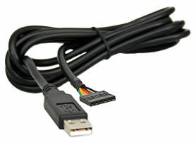
  3. I guess there is an option 3, as well. You could buy a USB to TTL UART cable and connect this to your board, instead of putting the USB connector on your board, if you wanted to get as simple as possible with both software and the PCB design. FTDI cable assemblies: https://www.ftdichip.com/Products/Cables/USBTTLSerial.htm.

\$\endgroup\$
4
  • 1
    \$\begingroup\$ Option 3 is really the same as option 2 -- the chip is hidden in the cable assembly. \$\endgroup\$
    – Dave Tweed
    Commented May 3, 2019 at 17:50
  • \$\begingroup\$ Ha! I looks like we typed up the same answer at the same time. No matter, this question will probably be closed anyway :-) \$\endgroup\$
    – bitsmack
    Commented May 3, 2019 at 17:51
  • \$\begingroup\$ @DaveTweed Yes, electrically it ends up the same. \$\endgroup\$ Commented May 3, 2019 at 17:52
  • \$\begingroup\$ @bitsmack Haha. Yes our answers are surprisingly aligned; but yours was faster, better written and has pictures, so I commend you! \$\endgroup\$ Commented May 3, 2019 at 17:54
3
\$\begingroup\$

The UART and USB peripherals are entirely separate entities.

  1. If you want simple UART, you can generally break out the TX, RX, and GND pins onto a connector, then connect these to an appropriate UART-enabled device. You need to configure both devices to match, as far as speed (baud rate), parity type, number of stop bits, etc.

  2. If you want your project to become a USB device it's more complicated. In addition to fairly stringent hardware guidelines, it'll need to handle all of the "under the hood" USB protocol stuff. ST makes available a USB Device Library, which can be found here. It takes a bit of learning.

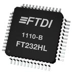
  3. A third option is to use a USB-to-UART converter. In this case, the converter handles all of the USB and UART protocol requirements. It takes simple UART from your microcontroller and pipes it to a USB host via a USB cable. You can build in circuitry on your board to handle the conversion, or you can buy an external converter that someone else has already engineered.

An example of an internal USB-Serial converter would be a FT232H. You'd need to add it and its supporting circuitry to your design:

USB_IC

An example of a pre-made converter cable would be here. In this case, you plug it into a USB port (on a PC, perhaps), and connect the other end to the UART pins on your device:

USB_adapter

These are just examples. There are lots of converters, both internal and external, to choose from.


By the way, don't simply hook UART signals to a USB connector. Not only will it not work, but the differing voltage levels may destroy your device and/or the remote device.

\$\endgroup\$
1
  • \$\begingroup\$ If I were to use the cable, do you know if any pull up resistors required? In the data sheet cable schematic, it says pull-up resistors are not fitted but I'm not sure if they are necessary? Also am I right that the TX on the cable is connected to the RX on my MCU and RTS to CTS similarly? On that note, are the RTS and CTS pins necessary for the cable? \$\endgroup\$
    – sophia_ash
    Commented May 4, 2019 at 13:27

Your Answer

By clicking “Post Your Answer”, you agree to our terms of service and acknowledge you have read our privacy policy.

Not the answer you're looking for? Browse other questions tagged or ask your own question.