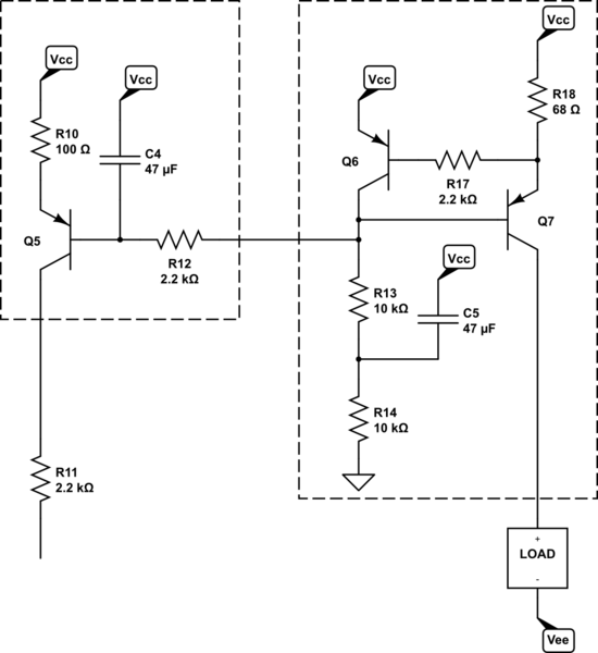
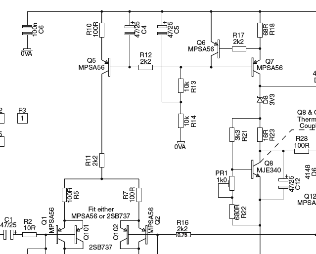
I gather you are talking about Figure 12.12 from the 5th edition. Here's the schematic redrawn, just slightly:

simulate this circuit – Schematic created using CircuitLab
You can see a very similar circuit to the portion of the above circuit within the right box in an answer I provided here. Note that I didn't include the equivalent of \$R_{17}\$ in that circuit (it's not strictly needed.) And note that it is based on NPN BJTs, instead. But the concept is about the same.
Resistors \$R_{13}\$ and \$R_{14}\$ turn on \$Q_7\$ and \$Q_6\$ by providing a current sink of about \$I_{R_{14}}=\frac{V_\text{CC}-2\cdot V_\text{BE}}{10\:\text{k}\Omega+10\:\text{k}\Omega}\$. Assuming \$V_\text{CC}\$ is on the order of about \$45\:\text{V}\pm 5\:\text{V}\$ this is on the order of around \$2\:\text{mA}\$.
The actual value of \$I_{R_{14}}\$ isn't that important, because the excess is handled by \$Q_6\$. The rest provides the needed base recombination current for \$Q_7\$, whose base-emitter junction is certainly now forward-biased.
\$Q_6\$'s base is pulled down by the emitter of \$Q_7\$, turning \$Q_6\$ on, as well. So both BJTs are definitely active. Ignoring \$R_{17}\$ for now, \$Q_6\$'s \$V_\text{BE}\$ "sets" the voltage across \$R_{18}\$, which will be one base-emitter drop.
So, assuming \$V_{\text{BE}_{Q_6}}=700\:\text{mV}\$, then \$I_{R_{18}}=\frac{V_{\text{BE}_{Q_6}}}{68\:\text{k}\Omega}\approx 10.3\:\text{mA}\$ and that also sets the collector current of \$Q_7\$.
Given that collector current, it is likely that \$V_{\text{BE}_{Q_7}}\ge 700\:\text{mV}\$ and that the base recombination current of \$Q_7\$ will be on the order of 100 times smaller (or still less), or about \$I_{\text{B}_{Q_7}}\approx 100\:\mu\text{A}\$. We already calculated \$I_{R_{14}}\approx 2\:\text{mA}\$, which is therefore far more than enough for \$Q_7\$'s base. The rest is disposed of by \$Q_6\$'s collector. So we can expect that \$Q_6\$'s collector current is also close to \$2\:\text{mA}\$ and that confirms the previous assumption that \$V_{\text{BE}_{Q_6}}=700\:\text{mV}\$. Q.E.D.
So the "LOAD" on the right is seeing a constant current source of about \$10\:\text{mA}\$ as a result of the circuit on the right.
(The base recombination current of \$Q_6\$ will be \$I_{\text{B}_{Q_6}}\le 20\:\mu\text{A}\$. \$R_{17}\$ is there to help protect \$Q_6\$ should the load wind up short-circuited.)
Moving over to the left side, now.
\$Q_7\$'s base voltage is pretty stable and will be approximately two \$V_\text{BE}\$ voltages below \$V_\text{CC}\$. (\$Q_6\$'s plus \$Q_7\$'s plus a tiny drop for \$R_{17}\$.) I expect it to be about \$1.5\:\text{V}\$ below \$V_\text{CC}\$. This \$Q_7\$ base voltage is then presented to the base of \$Q_5\$ via \$R_{12}\$.
Assuming no voltage drop for \$R_{12}\$ for a moment, we'd expect the emitter current of \$Q_5\$ to be about \$I_{\text{E}_{Q_5}}=\frac{1.5\:\text{V}-700\:\text{mV}}{R_{10}=100\:\Omega}\approx 8\:\text{mA}\$. This implies \$I_{\text{B}_{Q_5}}\le 80\:\mu\text{A}\$ and therefore a voltage drop across \$R_{12}\$ of \$180\:\text{mV}\$. This lowers the computed collector current for \$Q_5\$ towards about \$6\:\text{mA}\$. (No point in being overly-precise, though, so these numbers are only approximate.)
(Again, \$R_{12}\$ and \$C_4\$ provides some isolation and base voltage stability as well as some thermal and BJT variation handling.)
So \$Q_5\$ is just another current source. But with a set point that is a little different from \$Q_7\$'s, determined by the different emitter resistors being used by them.
\$Q_6\$ soaks up (via its collector) the excess current supplied via \$R_{13}\$ and \$R_{14}\$ (using \$C_5\$ to seriously stiffen up their current sinking behavior at AC.) This collector current is high, compared to the base current used by \$Q_7\$, so that the variations in \$Q_6\$'s \$V_\text{BE}\$ will only very slightly impact the base voltage that is passed over to \$Q_5\$.


