4
\$\begingroup\$

I was looking at a BeagleBone Black Cape and became curious on an input circuit to the BeagleBone GPIO (used for a NPN proximity sensor). Upon further reverse designing, I notice a // 220Ω shunt resistor (R1) with the LED. I have a basic understanding on diodes/LEDs (current limiting series Rs for LEDs) but I cannot understand the purpose for R1. So I cal'd the currents thru R1, R2 and the LED but after looking at the datasheet (PS2802) at the "forward current vs. forward voltage I am not sure if my cal'd currents are correct.

In short, the series current limiting R2 (1.2kΩ) I understand it's main purpose and how to calculate it's value but the shunt R1 (220Ω) purpose is confusing me.

My original question was just going to ask. What is the purpose for R1?

But now, my secondary question is (in general). Are my current values correct?

I hope I can become enlightened;-)
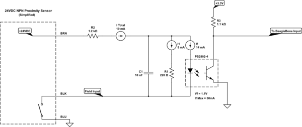
schematic

simulate this circuit – Schematic created using CircuitLab

\$\endgroup\$

2 Answers 2

2
\$\begingroup\$

The currents that you show appear to agree with a quick circuit simulation I did with LTSpice. Do note that the 1.2K and 200 ohm resistors are not acting like a normal voltage divider. Instead the input diode in the opto-coupler is tending to clamp the voltage drop across the 200 ohm resistor to about 1.1V. The current from the upper resistor gets split into one current going through the 220 resistor and the other going through the opto coupler input diode. The current split ratio will depend upon the forward voltage drop of the input diode in the opto coupler.

If you remove the opto coupler from the circuit then the two resistor voltage divider will not be clamped and the divider node will be at over 3.7V at a current of about 16.9mA in the divider.

The inclusion of the C1 capacitor in the circuit acts like a low pass filter to the input signal. The time constant is primarily due to the 1.2K resistor. The 220 ohm resistor helps to discharge the filter capacitor when the input signal goes low or open.

\$\endgroup\$
1
  • \$\begingroup\$ "The 220 ohm resistor helps to discharge the filter capacitor when the input signal goes low or open." The 220Ω R acting as a bleed-off now makes sense. It was staring at me the whole time and hiding in plane view. \$\endgroup\$
    – Steve
    Commented Jun 6, 2019 at 22:26
1
\$\begingroup\$

But now, my secondary question is (in general). Are my current values correct?

Your current values seem quite correct.
According the datasheet of the PS2802, \$I_f\$ = 13.5 mA gives a \$V_f\$ = +/- 1.2V.
1.2V across 220 ohm yields a current of 5.5 mA. 13.5 mA + 5.5 mA = 19 mA = \$I_{total}\$.
19 mA through 1.2 kohm gives a 22.8V voltage drop.
And 22.8V + 1.2V makes 24V.

The other way around, when you don't know \$I_f\$ and \$V_f\$ yet (and you don't have LTspice or that specific component in LTspice) you want an expression of \$V_f\$ that gives a corresponding \$I_f\$ (or the other way around) to be used in the FORWARD CURRENT vs. FORWARD VOLTAGE figure given by the PS2802 datasheet.

So, let's start with

1) \$I_{total} = I_f + I_{R1}\$

The voltage across the LED of the PS2802 is the same across R1:

2) \$V_f = R1 \cdot I_{R1} = 220 \Omega \cdot I_{R1}\$

Rewriting gives

3) \$ I_{R1} = \frac{ V_f }{ 220 \Omega } \$

The current through R2 is the input voltage minus the forward voltage, divided by R2

4) \$I_{total} = \frac{ V_{in} - V_f}{R2} = \frac{24V}{1200 \Omega} - \frac{ V_f}{1200 \Omega} = 20 mA - \frac{ V_f}{1200 \Omega}\$

Substituting 4 in 1 gives

5) \$ 20 mA - \frac{ V_f}{1200 \Omega} = I_f + I_{R1} \$

Substituting 3 in 5 gives

6) \$ 20 mA - \frac{ V_f}{1200 \Omega} = I_f + \frac{ V_f }{ 220 \Omega }\$

Rewriting gives

7) \$ I_f = 20 mA - \frac{ V_f}{1200 \Omega} - \frac{ V_f }{ 220 \Omega }\$

8) \$ I_f = 20 mA - V_f \cdot \frac{71}{13200} \frac{ 1}{\Omega}\$

Now you can add (\$ I_f, V_f \$) points to the figure called FORWARD CURRENT vs. FORWARD VOLTAGE. (You cannot draw a linear line through these points, because the FORWARD CURRENT axis is logarithmic.)
Where these points intersect the (e.g.) 25°C curve, that point gives you the exact \$ V_f\$ and \$ I_f \$.

\$\endgroup\$
1
  • \$\begingroup\$ Interesting on your approach, that's a big help for me. \$\endgroup\$
    – Steve
    Commented Jun 6, 2019 at 22:27

Your Answer

By clicking “Post Your Answer”, you agree to our terms of service and acknowledge you have read our privacy policy.

Not the answer you're looking for? Browse other questions tagged or ask your own question.