0
\$\begingroup\$

for my master thesis I'm investigating the EMI of a 3-phase inverter, wich drives a PMSM. The inverter's structure is the common 3-Phase DC/AC Voltage Source Inverter and it uses EPC2020 GaN transistors at 100 kHz switching frequency. For my investigations the system needs to be in a stationary state with exactly periodic currents and signals, hence no closed loop control is used.

Instead I only set the desired stator voltage and frequency and let the motor do its thing. For startup I slowly increase the stator frequency and at the same time increase the voltage my inverter produces to compensate for the higher back EMF at higher frequencies.

So far so good, although this method is not practical, it lets the motor run at my desired electrical frequency of 50Hz in an idle state, but the phase currents are concerningly high.

The system currently runs with a DC rail voltage of 20V. The DC current going in the inverter is peaking at about 5A. The phase current of the PMSM on the other hand is peaking at nearly 20A. Hence my conclusion the majority of this current is reactive current between the motor and my DC link cap. So now my real question: How do I reduce that reactive current? From my understanding of synchronous machines, the reactive current is not needed for torque built up and should be controlable through the ratio of stator voltage and induced back EMF. So if I adjust the absolute value of my stator voltage it should be possible to reduce the reactive current to a minimum, while still drawing the real current needed to drive the motor.

But that's unfortunately not what I experienced until now. If I increase the stator voltage, the reactive current gets bigger. If I reduce it, the current does reduce a bit, but before it gets reduced significantly, the motor stops, so somehow also the real current got reduced, what I find counterintuitive.

I plotted one phase current and the DC current for one whole period, you can take a look. They also don't look like I expected, but I have no explanation on why that is...

So I know this may be an unusual use case, but maybe there are some machine experts out there, who may guide me in the right direction ;)

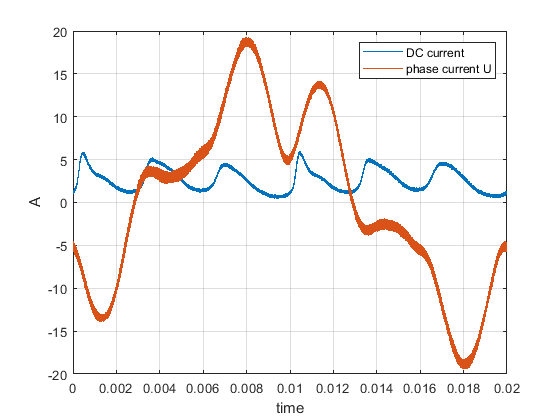
Phase and DC current

\$\endgroup\$
8
  • \$\begingroup\$ Have you ever heard about FOC algorithm? Also, for torque control a current control is nedded, voltage control is not so important for motor control. Why to reinvent warm water? \$\endgroup\$ Commented Jun 26, 2019 at 7:33
  • \$\begingroup\$ Thanks for your answer. Yes I know about FOC, but for my case I don't need a closed loop algorithm, but a deterministic control signal. I just want to put a voltage on it and want it to rotate, even though this is not the way you would normally do it. \$\endgroup\$
    – raduur
    Commented Jun 26, 2019 at 7:38
  • \$\begingroup\$ You will get better performance under load disturbances with feedback. infineon.com/cms/en/product/power/motor-control-ics/… VFD is good but with FOC even better with PFC and current feedback to reduce reactive current. Hall and Angle sensors are used for most efficient sine drive. \$\endgroup\$
    – D.A.S.
    Commented Jun 26, 2019 at 7:46
  • \$\begingroup\$ Yeah the performance would be better with FOC, no doubt. But as I tried to explain, closed loop control is not an option in my case. \$\endgroup\$
    – raduur
    Commented Jun 26, 2019 at 9:58
  • \$\begingroup\$ By "stationary state," do you mean the shaft is prevented from turning or do you mean "steady state" - constant speed, neither accelerating nor decelerating? Is the shaft free or connected to a load? What kind of load? What is the motor rating plate information, rated voltage, frequency, current, speed or number of poles, mechanical output power? Are the voltages and currents balanced among the three phases? Is the inverter a commercial product? \$\endgroup\$
    – user80875
    Commented Jun 26, 2019 at 10:24

1 Answer 1

1
\$\begingroup\$

It sounds to me that you are running an open loop "Volts per Hertz" algorithm similar to what you could run with an induction machine. The problem you are seeing, I think, is that a permanent magnet synchronous machine has very little damping (contrary to induction machines), and your rotor is oscillating pretty wildly. When your currents are high, this is from a high phase lag on the rotor, which makes high torque, which requires high current (and there is a lag involved because of the machine inductance). Then the rotor accelerates, overshoots the synchronous speed and phase, and the current drops, then the stator field catches up, overshoots the rotor, etc. You don't seem to be breaking synchronism (motor would stop and your currents would skyrocket), which is something to be thankful for. To confirm or disprove my theory, you could look at rotor speed. I suspect you will see the oscillations around your fundamental frequency.

You make this claim: "For my investigations the system needs to be in a [steady] state with exactly periodic currents and signals, hence no closed loop control is used." I think you are implying that a closed loop control cannot get you exactly periodic currents and signals, but the reverse is true. In my experience, you will not be able to get steady, uniform speed on a permanent magnet synchronous machine without using closed loop control. I should mention that when I say "closed loop control", I mean you are closing the loop around speed. You have to have a position sensor (or a position sensing algorithm) to do this because you have to know where the magnetic axis of the rotor is in order to maintain your stator field at a constant phase with respect to the rotor field. If you do this, and your load is constant, then you will have steady currents and steady speed.

As I am thinking about how you would make your setup work, I think you have to have damping to eliminate the resonance. One (impractical) way to get damping would be to rebuild your motor with damper bars on the rotor. But if your shaft load could provide damping, maybe this would work, too. You would need a torsional damper with viscous damping behavior as your shaft departs from synchronous phase. This might be more attainable because you can obtain such dampers commercially (maybe they come this small?) or even perhaps build one? You would have to compare that effort to adding a position sensor (if you don't already have one) and a closed loop control circuit.

Just to "close the loop" on another statement, you always have reactive current in a pmsm. Because you have inductance in the stator, to get current on the quadrature (i.e., torque producing) axis of the rotor reference frame, you have to put in leading terminal voltage. Measuring at the terminals of the motor, the voltage will lead the current in motoring. If you could somehow measure the back-emf of the motor (you can't), and you had the system under closed loop speed control, you could get the terminal current to line up directly with the emf of the motor, but, again, from what you can measure at the terminals, you would find you have to put in leading voltage to accomplish this. You can see some phasor diagrams at this link: http://electricalacademia.com/synchronous-machines/synchronous-motor-equivalent-circuit-phasor-diagram/

I am sorry I cannot come up with something more useful than this, but as I understand what you are working with, this is the best I can do.

\$\endgroup\$
1
  • \$\begingroup\$ Thanks for your in depth answer. You could be right regarding the oscillaitons the rotor makes. The motor does have a rotation sensor, I might check it out to prove this. Your suggestions for dampening and using closed loop control are definitely good. But considering I have very limited time for my thesis and my main focus is on EMC, they are unfortunately out of my reach. But nontheless you provided me a bettter understanding ;) \$\endgroup\$
    – raduur
    Commented Jul 10, 2019 at 8:09

Your Answer

By clicking “Post Your Answer”, you agree to our terms of service and acknowledge you have read our privacy policy.

Not the answer you're looking for? Browse other questions tagged or ask your own question.