0
\$\begingroup\$

I have a computer fan controller circuit which uses an microcontroller to convert an analog signal from a potentiometer to control the speed of an computer fan (PWM controlled) and indicate the rough speed percentage with 4 LEDs.

When I use my circuit on the breadboard it works perfectly, but when I use the etched circuit it flickers for a second or two then shuts down completely.

Background

Here is the circuit:

As you can see it's using a 12V supply and then a voltage regulator to supply the microcontroller with the needed 5V. Then I have the fan hooked up to the 12V supply and the control cable hooked up to the microcontroller.
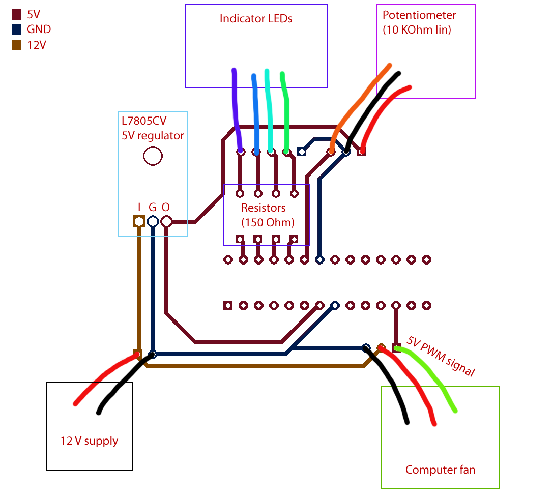
circuit

When I'm using the circuit in the breadboard I connect the resistors and the potentiometer to the breadboard via the IC holder on the etched circuit to make sure there isn't something wrong with the components or soldering. Then I supply the microcontroller with 5V from a stabilized DC power supply.

Then I measure the 5V PWM signal that should go to the fan with a multimeter. Everything works like expected, the LEDs light up when I turn the potentiometer and the voltage measured goes up.

Here is what the circuit looks like in action from the breadboard. (I'm measuring the PWM output with the potentiometer on these images) 0 percent:
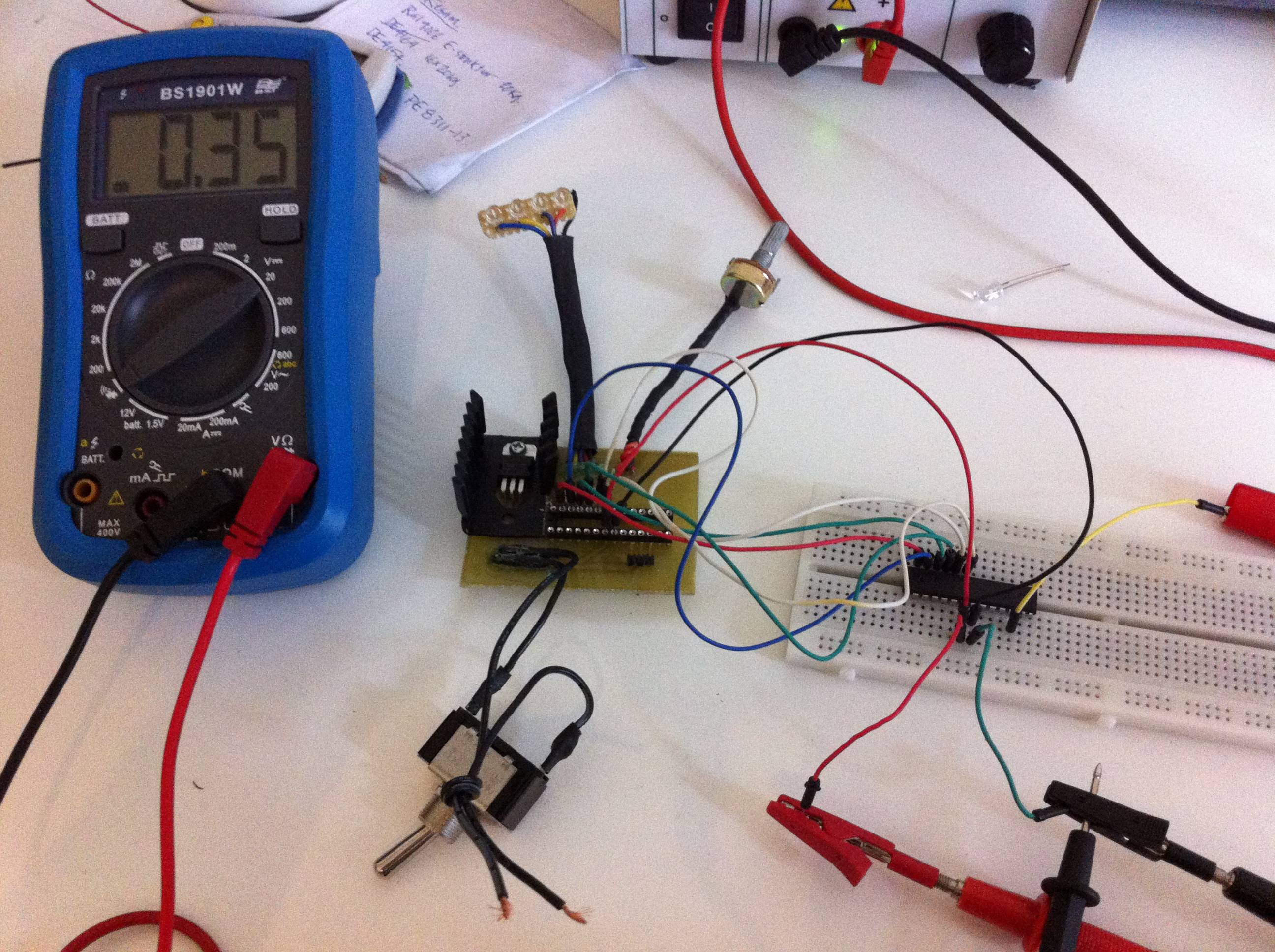
All turned down

Around 50 percent (Yes, the code that lights the LEDs needs to be fine tuned :P)
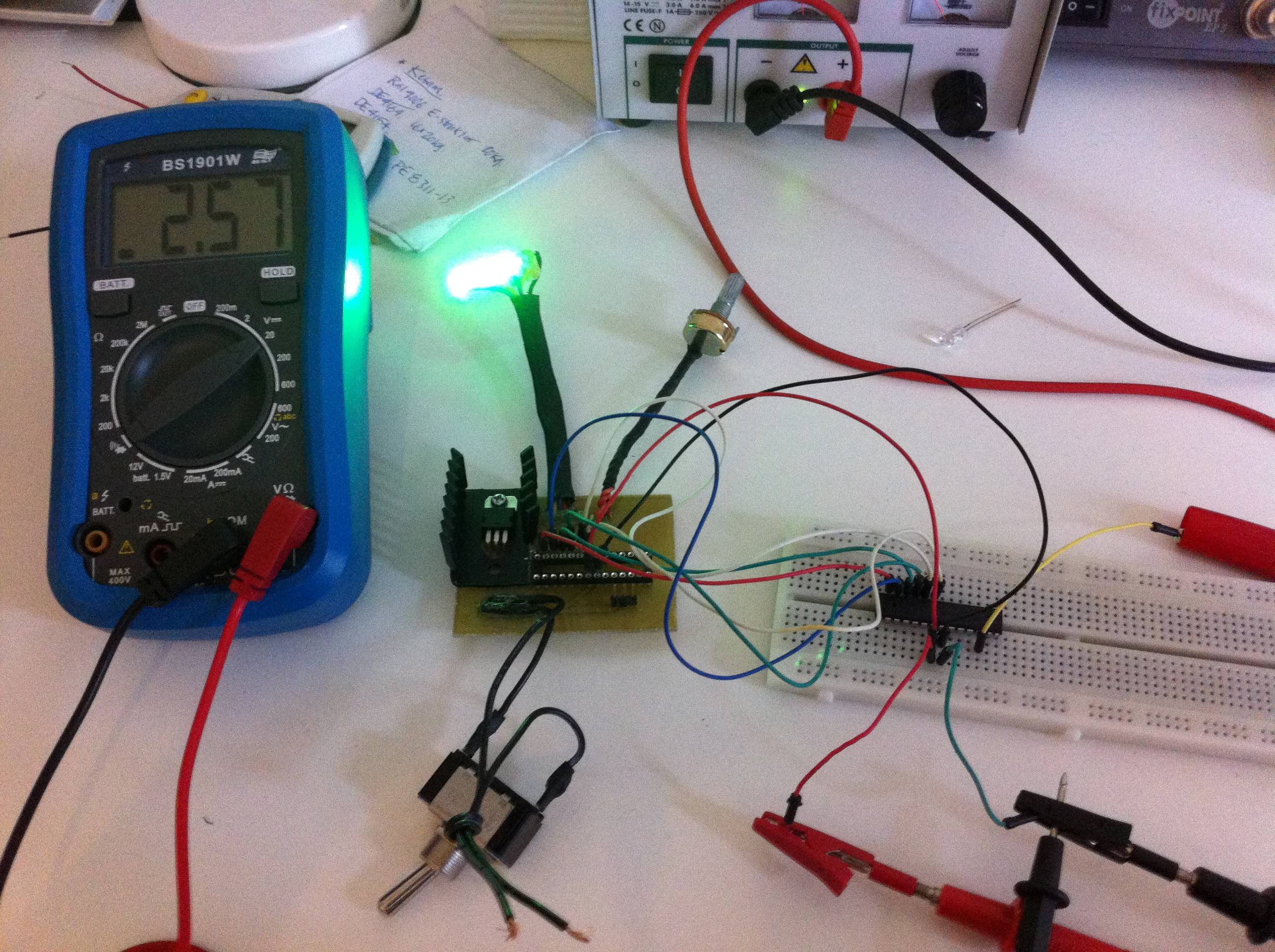
50%

100 percent!

100%

So the only difference is essentially the supply. When I put my microcontroller on the circuit and connect my DC power supply with 12V it flickers and stops working after a second or two.

Here is what the circuit looks like in action in the circuit itself with 12V applied across the supply. It stays like this even if I turn the potentiometer. I have checked that the regulator is regulating successfully and that the microcontroller VCC pin has 5V applied.
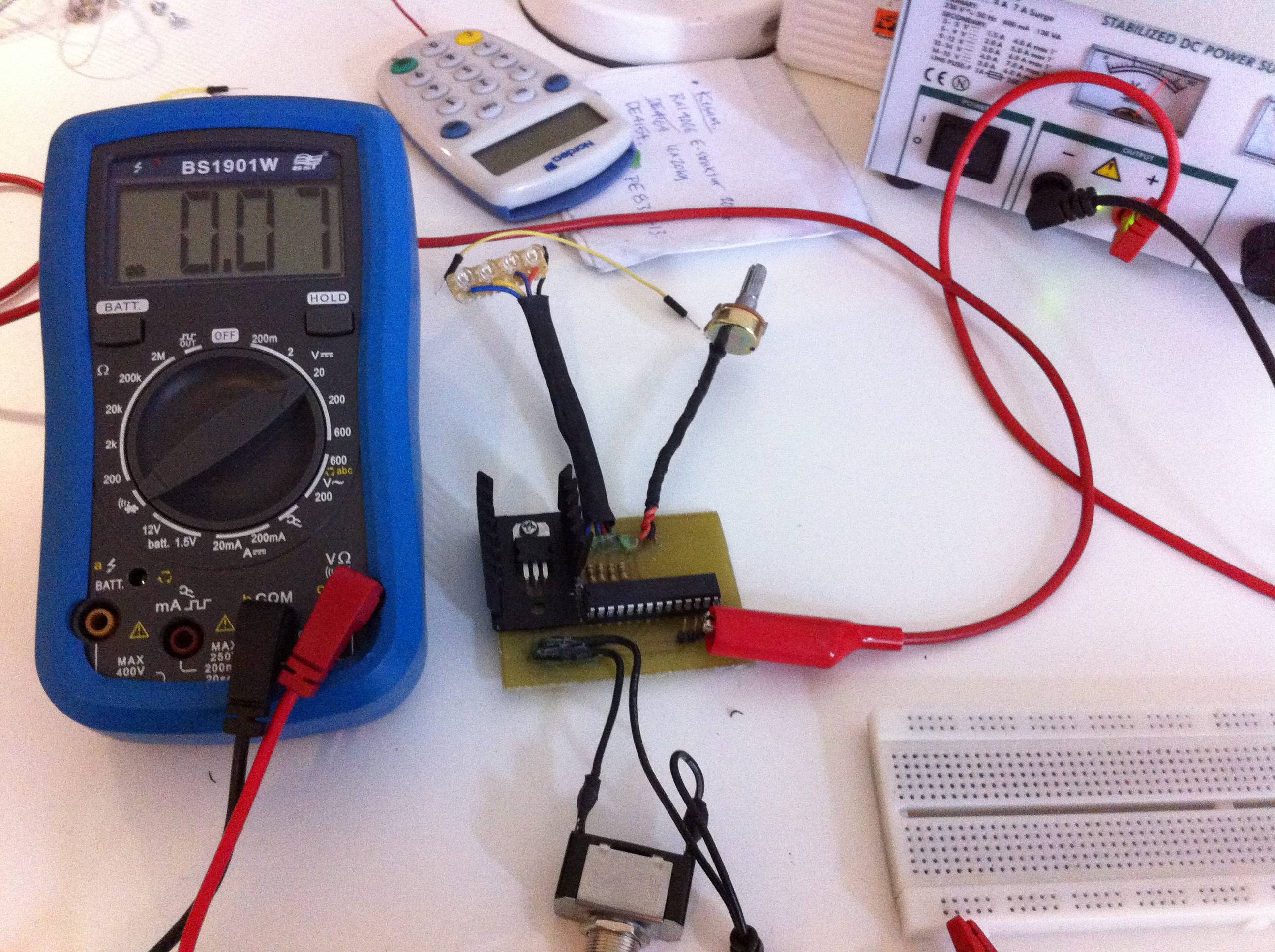
No, no. Not working.

What could be the problem?

This is the first circuit I have designed and etched, so no need to tell you that I'm a novice. The only thing I can come up with that would be a problem is that different supplies share the same ground. Is there something else that could be the problem?

\$\endgroup\$
2
  • 1
    \$\begingroup\$ Where are your output caps for that regulator? You should put at least a 1uF cap across Vout and GND, and another across Vin and GND. Mind the voltage ratings on the caps too. \$\endgroup\$ Commented Oct 17, 2012 at 12:43
  • \$\begingroup\$ They were not there, which was the problem :) See my last comment of the accepted answer. \$\endgroup\$ Commented Oct 17, 2012 at 13:36

1 Answer 1

4
\$\begingroup\$

Is your circuit diagram complete? If so I miss the mandatory decoupling capacitors!

You don't mention the type of microcontroller you use, from the diagram I assume an 28-pin PIC like a 16F876 or 18F242 or the like. Such chips have two ground pins, which MUST both be connected to ground. You seem to use the chip's ground pins as a wire to connect your two grounds, which is not a good idea.

Does the chip have an internal reset and did you configure it? And idem for the oscillator?

\$\endgroup\$
9
  • \$\begingroup\$ The circuit you see on the photos are identical to the diagram. I'm using an AVR ATMega328P (see datasheet: atmel.com/Images/doc8271.pdf). Does decoupling capacitors need to be used when there are different supplies using the same ground? \$\endgroup\$ Commented Oct 17, 2012 at 9:19
  • \$\begingroup\$ About internal reset; do you mean brown-out reset? Then the answer is no, no brown-out is set up. About the oscillator; it's using the internal 8Mhz oscillator with a clock divide of 8. \$\endgroup\$ Commented Oct 17, 2012 at 9:38
  • \$\begingroup\$ Decoupling capacitors are always needed in the same sense that you must always look left and right before crossing a street. You can sometime do without, but you won't last long. Add at least 100nF at the input and output of the 7805, 100uF at the input, and 100nf at the power pins of the chip. And connect ALL power pins! including AVCC and probably AREF. \$\endgroup\$ Commented Oct 17, 2012 at 9:40
  • \$\begingroup\$ Reset: did you configure pin PC6 for reset or for I/O? And BTW: is there a watchdog in this chip, if so, did you disable it? \$\endgroup\$ Commented Oct 17, 2012 at 9:42
  • \$\begingroup\$ PC6 is set to default, which is reset. This is what the datasheet says about watchdog when using internal oscillator: "When this (internal) Oscillator is used as the chip clock, the Watchdog Oscillator will still be used for the Watchdog Timer and for the Reset Time-out." \$\endgroup\$ Commented Oct 17, 2012 at 9:45

Your Answer

By clicking “Post Your Answer”, you agree to our terms of service and acknowledge you have read our privacy policy.

Not the answer you're looking for? Browse other questions tagged or ask your own question.