1
\$\begingroup\$

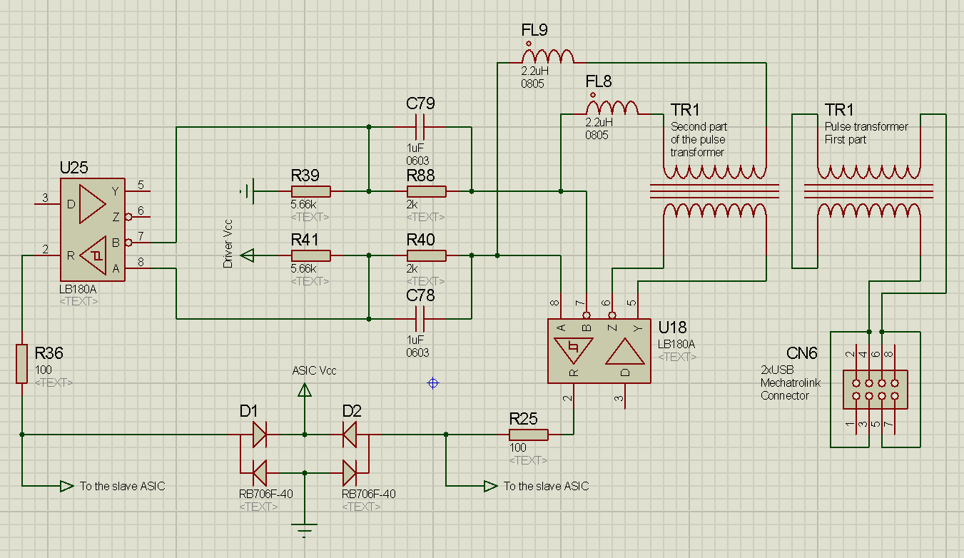
I'm trying to reverse-engineer Mechatrolink-II front-end circuitry. Its physical layer is simple RS485 (with isolation transformer) running at ~10Mbps. Here is the schematic I obtained from the PCB of a Mechatrolink-II-compliant device.

Schematic

And I have two questions about it.


The transformer

Proteus does not have exact models I needed, so two transformer models (TR1s) actually represent a single "Mechatrolink-exclusive pulse transformer" (http://products.mechatrolink.org/en/product/detail/id=170), in other words, their cores are not separate.

  1. Now suppose I want to attach a sniffer (or even a slave at some point in future) to the existing bus. Obviously, I can't buy this exact transformer (at least less than several hundreds of them), but I've plenty of Ethernet transformers rated for (at least) 10BASE-T, which is, speaking of pulses, roughly the same 10Mbps and the windings are the same too. Can I use them?
  2. Can I omit the isolation transformer altogether during prototyping, taking into account relatively short length of the sniffer's cable and a floating supply (that can share ground with other devices, if needed)?
  3. And also, why Mechatrolink engineers might have chosen to place two windings on the bus side and connect them with a PCB trace, instead of a single winding like in Ethernet?

Two transceiver ICs?

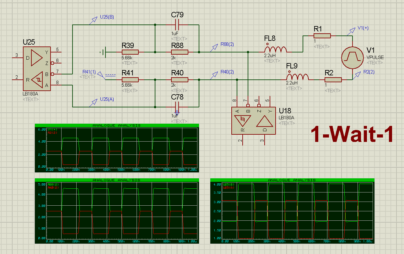
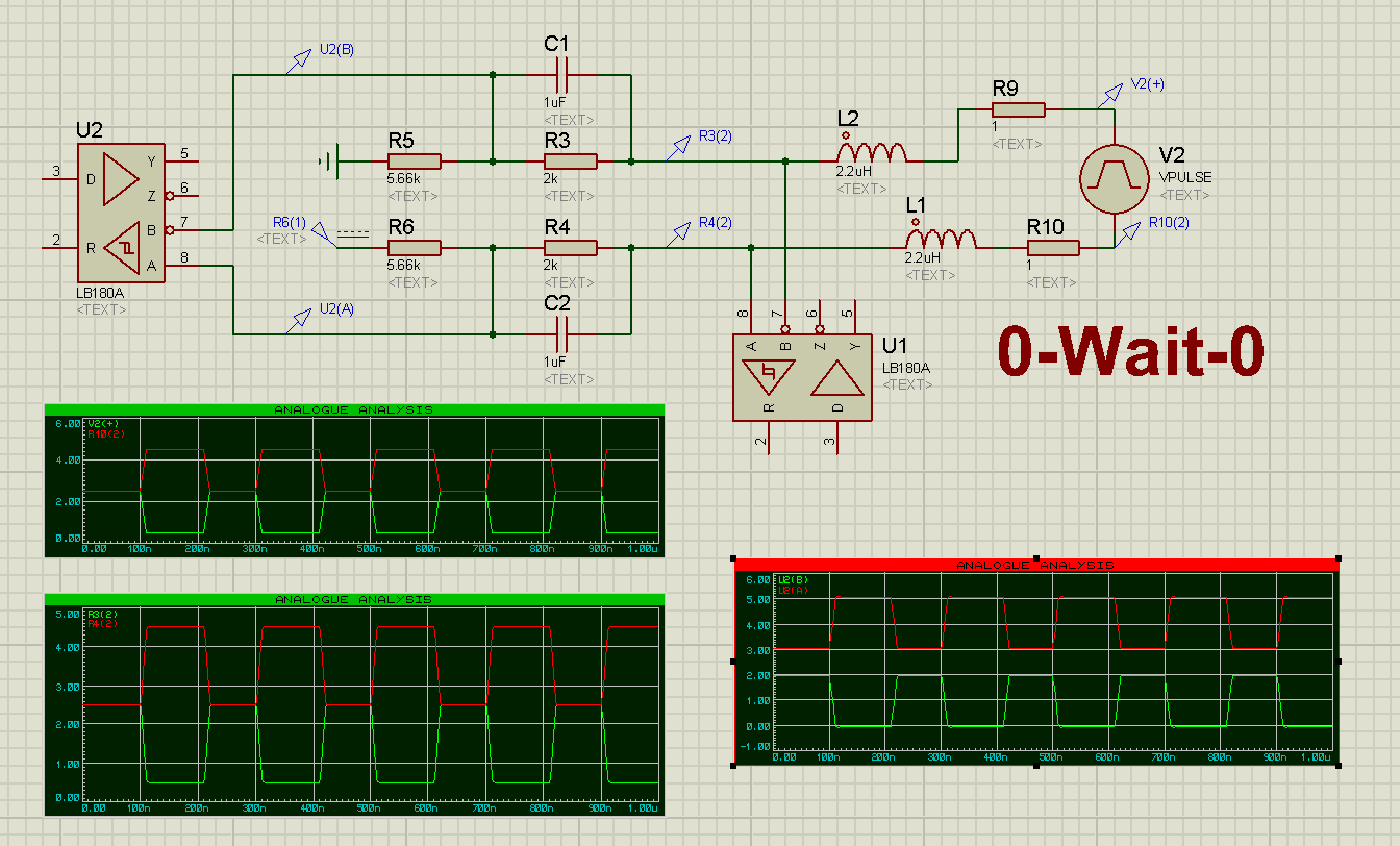
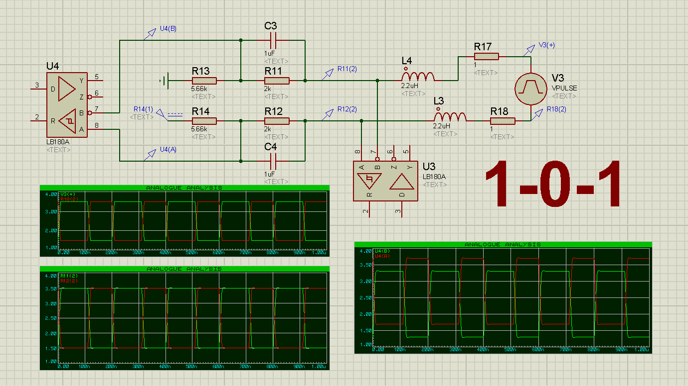
I can't quite understand the purpose of all that RLC-stuff going on after the transformer. If there was only one IC, I would I've thought it's there to correct transformer imperfections (overshoot etc). I've simulated the behavior of the circuit, assuming that the transformer replicates incoming signal good and outputs almost square (<10nS rise/fall time) 100nS pulses (which, as far as I understand, it should, if chosen right).

Here are 3 possible scenarios (scaling Proteus screenshots is always a pain, open them in full size). Upper-left plot is the pulse source, below are U18's A and B, on the right side are U25's A and B, color is consistent.

1-Wait-1 0-Wait-0 1-0-1

  1. In any case, U18 will decode the bits just fine, am I right? Then why is there U25? Their receivers' outputs are connected to the same ASIC, U25's Y and Z appear unconnected.
  2. By the way, how does the system distinguish WAIT and a repeating bit (receiver output obviously lacks the third state)? Only by using a fixed (or transmitted) packet length protocol?
\$\endgroup\$
3
  • \$\begingroup\$ Welcome. Voting to close this question as being much too broad in scope and off-topic. Way too many questions about what is mostly reverse-engineering. OP can learn much by reading various serial protocols. \$\endgroup\$
    – user105652
    Commented Aug 4, 2019 at 3:13
  • \$\begingroup\$ Where did you find the transformer arrangement? There should be a delay/phase difference beeween two receivers. \$\endgroup\$ Commented Aug 4, 2019 at 6:37
  • 1
    \$\begingroup\$ @MarkoBuršič Well, the exact arrangement is unknown, since technical papers are available only for Mechatrolink members. But I have the board. Here is the pinout of the transformer, based on this pinout I've deduced the arrangement. imgur.com/a/wcXSGLP \$\endgroup\$ Commented Aug 4, 2019 at 14:49

2 Answers 2

2
\$\begingroup\$

two receivers: my guess is since mechatrolink ii comes in two flavours - 4Mbps and 10MBps, they are probably just doing some filtering in one of the receiving paths.

funny, i also spent some time reverse engineering it about a year ago and then suspended the project. just yesterday decided to revisit it.. back then i captured some dumps from the bus without any isolation, just plugged it directly into rs485 receiver. it worked, but there were some noise when a drive turns on...

\$\endgroup\$
1
  • \$\begingroup\$ This does not answer the OP question, but is a "me too!". \$\endgroup\$ Commented Aug 13, 2019 at 22:28
1
\$\begingroup\$

Well, I guess I've found most of the answers myself.

The transformer

  1. Their inductance range is rather broad, I've found on the market anything from 0.4uH to 350uH, though some are marketed as just "LAN transformer"s, not exactly Ethernet. According to simulation 100-350uH should be fine for 10Mbps. Also Ethernet signal magnitude equals 2.5V, while for RS485 it usually equals ~1.5V, so Ethernet transformers won't saturate. But I've also found that you don't have to use ethernet transformers at all, you can actually still buy Q10RTS8 transformer and TOKIN-614 choke (is connected in series with the primary winding). Those items were used in some of the older Mechatrolink-II boards.
  2. Out of the question now, since the transformers are available. Obviously, this could potentially lead to ground loops (and high common-mode voltage), reflections etc.
  3. This one is still open, though it's not of a great importance.

Two transceivers

  1. I had a chance to take a look at another Mechatrolink board and it does not contain inductors/caps like FL8, C79 etc. Only a resistor divider is left, therefore it must be just an attenuator, no phase-related magic. Probably it's present (along with the second transceiver IC) for the system to be aware of the signal level. Also it might be used to determine WAIT state, though I think it's unlikely, because it allows to do so only after a positive bit (see simulation plots). Anyway, for a sniffer one transceiver will be fine too.
  2. The hysteresis of the receivers is in fact required to transmit several consecutive equal bits at full bus speed. You can determine WAIT state coming after any bit if you add third receiver that is biased by a similar resistor network, but complementary to U25.
\$\endgroup\$
1

Your Answer

By clicking “Post Your Answer”, you agree to our terms of service and acknowledge you have read our privacy policy.

Not the answer you're looking for? Browse other questions tagged or ask your own question.