3
\$\begingroup\$

I'm coming from the world of software, where I feel quite at home - I spend a lot of time writing code. I do not feel at home in the world of electronics and designing circuits. I really REALLY would like to learn more about electronics and designing circuits. I know I could be good at it, too, if only I had the intuition for it - which I'm so obviously and desperately lacking.

One project I thought up to try and bridge the gap between these two worlds is by programming a Microchip, specifically the PIC16F88 (not super attached to this model in particular, I just picked this one because from what I've heard it's relatively straight-forward to play around with). I'm sure that once it comes to writing code I'll be more comfortable, but first I'd like to build the circuit.

I'm guessing there won't be a lot of components involved. I was thinking the first thing I'd like to try and do is to simply have the microchip toggle an LED on and off at 1-second intervals. Cool, so now what? That's kind of where my problem starts.

My first impulse is to design the circuit the same way I'd design a simple LED-light-up-circuit. Pick the desired current (in the case of a single garden-variety LED ~20mA), determine the corresponding voltage drop from the LED's datasheet, subtract the voltage drop from the total voltage provided by the power supply / battery, and finally use Ohm's law to determine the required resistance to limit the current to the desired value.

Well, how much current does an IC draw? How much is too little, how much is too much? I realize an IC is a completely different animal from an LED, but that's where my understanding ends. Obviously there must be something wrong with my approach - the datasheet doesn't even mention current (at least not in any terms I can understand), however, other people are obviously able to design and power this chip just fine. I'm aware that how much current an IC draws depends on the IC and the application, and that there's things like Quiescent current and Input Sink / Output Source currents (just because I know these words doesn't mean I understand them fully) - so where do I find this information? Concrete numbers? Should I even be using this naive approach to build this more complex circuit? I know there isn't a conspiracy trying to hide information from me, but honestly sometimes in my journey through electronics and circuit design it feels as though there is hidden knowledge that's being denied to me.

If anyone can shed some light on my issue(s), or provide an intuition or general guidelines for knowing how to find the information you need to build a circuit, I would appreciate it. Also, if possible, explain it like I'm five years old.

\$\endgroup\$
1

4 Answers 4

4
\$\begingroup\$

Your LED design approach is generally correct.
A LED data sheet might suggest 20mA current is a maximum value. A modern, efficient LED is very bright with 20mA. In darkness, with dark-adapted eyes, you might be able to see the LED begin to glow with 0.05 mA.
A rough design current for an efficient LED might be around 1 mA...that won't stress the PIC's I/O pin. 20mA is requiring the I/O pin to work rather hard.

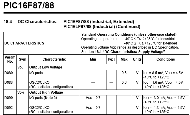
Microchip's data sheet for PIC16F88 shows the DC specifications that set some limits on GPIO (input/output) pin voltages and currents (a portion snipped below). The pertinent part is \$V_{OL}, V_{OH}\$ for I/O ports:
portion of Microchip 16F88 data sheet
It appears that an I/O pin can sink current (8.5mA) with less stress than it can supply current (1.6mA). These are not limits, but are a single data point within the maximum limits stated elsewhere (Section 18.0 states that maximum current on any one I/O pin shouldn't exceed 25mA).
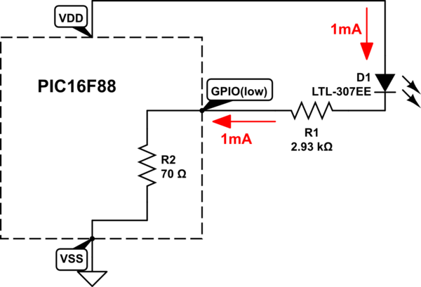
Sinking-better-than-sourcing is a common trait of GPIO output pins. So you're better off to sink...that means lighting up a LED by pulling current to ground - the LED's anode is attached to the +5V DC supply, and the GPIO pin pulls it ON by switching from logic high to logic low, through a series-connected resistor.

Example design:
A LED (when lit) requires about 2V when 1mA flows. Look to the LED's data sheet.
The PIC is powered from a +5v supply, which is also the point from which the LED anode draws its current. So VDD is +5v compared to VSS at zero volts.
A GPIO pin is set as "OUTPUT" and is pulled to logic LOW to turn on the LED.
The series resistance for 1mA LED current would be \$ (5.0 - 2.0)\over (.001)\$. That's 3000 ohms.
A more exact solution might account for the internal ON resistance of the PIC's I/O pin. This would be the ON-resistance of a N-channel MOSfet.
The data sheet (above) suggests this resistance is \${0.6V}\over{8.5mA}\$, about 71 ohms.
So a proper series resistor would be \$ 3000 - 71\$ ohms. But you wouldn't notice the difference in LED brightness compared to a 3000 ohm resistor.

schematic

simulate this circuit – Schematic created using CircuitLab
Note that a blue LED requires more voltage to light up than a RED LED, perhaps 3.4V instead of 2.0V....NO current flows until you exceed a LED's turn-on voltage. It is current that produces light. If your DC supply was low (perhaps 3.3V), the blue LED could not be reliably lit.

Well, how much current does an IC draw? How much is too little, how much is too much?

The PIC itself will draw current from its DC supply just to operate. Current flow depends a great deal on how fast it is operating...the data sheet can be confusing and has many charts showing current pulled from the DC supply under many operating conditions. While asleep, with no clocks running, it may pull a few microamps. A fast clock (20 MHz) with +5V supply might pull 5mA.

In the example circuit with LED ON, and a 20MHz clock, 5mA might enter VDD pin. This current would also exit VSS pin. But the VSS pin would also include the 1mA LED current, so 6mA exits VSS. From the power supply, 6mA flows.

Data sheet section 18.0 shows maximum limits. These are pain-of-death limits. For VDD, VSS, the limit is 200mA. That'd be one very hot PIC!. How could so much current flow? If you tried to light up many LEDS very brightly with all the available GPIO pins, with small-value series resistors (like zero ohms), a great deal of current might try to flow.
A caution regarding GPIO pins. They default to input rather than output. A GPIO pin can float around at any voltage between VDD and VSS. The electric field of a hand waving over the chip can change its voltage. It is not good to have a GPIO pin float near half-way between VDD-VSS. Excess current can flow. An unconnected input pin should be dragged down to VSS or dragged up to VDD. Dragging might be done with a resistor, in case the pin gets set to "output".

\$\endgroup\$
3
  • \$\begingroup\$ Thank you very much @glen_geek for walking me through the process. I will have to digest this for a while. I will mark your answer as the accepted answer in a while, just to encourage more people to chime in. \$\endgroup\$
    – Paul M.
    Commented Aug 31, 2019 at 17:12
  • \$\begingroup\$ Regarding input dragging - one strategy that doesn't require any external components is to enable weak pullup mode in software. This is commonly done if efficiency is of critical importance and the port output driver has more quiescent current than the input driver, or if there's concern that enabling the output drivers may create contention when the line state is not well-known. \$\endgroup\$
    – Reinderien
    Commented Aug 31, 2019 at 19:34
  • \$\begingroup\$ @Reinderien Yes, weak pullups serve this purpose nicely. The 16F88 is odd: weak pullups are available only on PORTB, but they properly default to OFF. No weak pull-ups on PORTA. You are able to let PORTA pins remain as their default analog inputs: there is no risk of half-Vdd shoot-thru current so long as they are not changed to (floating) digital inputs. \$\endgroup\$
    – glen_geek
    Commented Aug 31, 2019 at 20:55
2
\$\begingroup\$

You need a fixed-voltage power supply, not a simple resistor like an LED. This is because the current draw on the IC changes depending on load. For example it will draw more if you are sourcing an LED on an output while the output is "ON". This means the required resistance changes (not to mention that LED's are "constant current" devices where IC's are "constant voltage" ones).

This is why resistor-divider circuits are poorly suited to powering IC's. Best thing to do is to use a linear regulator (like the LM1117-3.3) or use a SMPS module with the desired output max current and constant voltage.

There are tools out there like TI's Webench that can help you design power supplies based on input. To get the current you need to look at worst-case for all the components it will power, then add some overhead to that.

\$\endgroup\$
1
  • \$\begingroup\$ Thank you. The distinction between "constant current" and "constant voltage" devices was especially helpful. \$\endgroup\$
    – Paul M.
    Commented Aug 31, 2019 at 15:58
2
\$\begingroup\$

According to that device's specsheet, it accepts a supply of 2-5.5V. Your first decision is what voltage you want to give it. This decision is based on a whole pile of things. In your case many don't apply - you won't yet care about efficiency, and you don't have external devices to consider. The "easy" thing is to just pick 5V, which can be output by many cheap, standard power supplies, or even a USB port.

Another consideration is what you're doing for your bench setup versus what you're doing for production. You don't have production in mind, really, so for your bench: what is your power supply? Do you have a wall-wart-style power supply? Are you using your computer's USB port? Do you have a $10,000 rack-mount lab-grade power supply? What do you have on hand? Are you putting this thing in a breadboard?

Do you have a programmer, such as a PICkit? It has a particular way that you need to wire the power supply. Will you be using the MPLabX IDE?

The answers to these questions will become clear given more experience, but for now the safe and easy thing to do is:

  • Find or buy the cheapest wall-wart-style 5V power supply that you can
  • Strip its barrel off, and run the wires to your breadboard
  • Verify the polarity with your multimeter
  • Connect it according to the guide in the PICkit documentation
  • Use MPlabX

If you fry your chip, or your supply, no big deal. They're both cheap. This also avoids the possibility of frying your laptop's USB port.

As to current... the relevant info you need is in chapter 19. It spells out typical current against operating frequency and oscillator mode. So you need to know what your oscillator mode is, and what frequency you're running at, to be able to get a vague picture of how much current your device is going to draw.

That device current is not the only thing you need to consider. You're also going to be connecting your LED + resistor directly to an output port, so you need to check figures 19-18 through 19-21. These talk about maximum port output for both the high (H) and low (L) levels.

\$\endgroup\$
5
  • \$\begingroup\$ Thanks for the feedback, and sorry for not mentioning the pertinent information in my original question. Yes, I do plan on doing this on a breadboard. I do have the PICkit 3 programmer and I've already installed MPLabX and the appropriate compiler. As far as power supplies go, just the other day in fact did I retrofit a wall-wart power supply in the way that you describe, so that it interfaces with the breadboard. The label on the side says "OUTPUT: DC 5V/350mA", however, when power the breadboard it's more like 8-9V. I'll take a good look at chapter 19. Thanks again! \$\endgroup\$
    – Paul M.
    Commented Aug 31, 2019 at 16:03
  • \$\begingroup\$ Be very careful. You might not present enough load to lower that 8-9V down to a voltage that's safe for your PIC. There are ways around this - you can add a simple resistive shunt between the leads of your supply. Start at 10k and go down until your voltage is at a good level. \$\endgroup\$
    – Reinderien
    Commented Aug 31, 2019 at 16:11
  • \$\begingroup\$ Good to know. Is that a general rule of thumb, that these wall-wart power supplies list a lower voltage than they actually supply? Furthermore, is that the expected behavior - that the voltage supplied by the wall-wart is dependent on the load? Thanks for your time. \$\endgroup\$
    – Paul M.
    Commented Aug 31, 2019 at 16:20
  • \$\begingroup\$ Another question, I'm looking chapter 19, where the various figures refer to "IDD" or "Typical IDD". What is "IDD"? It seems to be measured in or equivalent to amperage / current. Is this just another word for current? \$\endgroup\$
    – Paul M.
    Commented Aug 31, 2019 at 16:25
  • \$\begingroup\$ Let's please continue this in chat - chat.stackexchange.com/rooms/98131/… \$\endgroup\$
    – Reinderien
    Commented Aug 31, 2019 at 17:48
2
\$\begingroup\$

Most ICs (and most things electrical) are designed to operate from a specific voltage, or range of voltages, and will draw whatever current they require - there is no need for the user to limit the current.

LEDs are an exeption to this. Their chemical composition, colour, temperature, and other things determine the voltage across the LED when lit. If the applied voltage varies slightly from what the LED wants, the current through the LED will vary, so for proper, safe, operation, we have to control the current through the LED, rather than the voltage across it. The easiest way to do this is to connect a resistor in series with the LED.

\$\endgroup\$
1
  • \$\begingroup\$ Bennet I see. That angle does shed some light on my misconceptions. Thanks for this! \$\endgroup\$
    – Paul M.
    Commented Aug 31, 2019 at 16:04

Your Answer

By clicking “Post Your Answer”, you agree to our terms of service and acknowledge you have read our privacy policy.

Not the answer you're looking for? Browse other questions tagged or ask your own question.