There are some decent answers here, but there's a flaw in your understanding, and it's unclear who's wrong - you or your professor.
"I'm taking a computer system design course and my professor told us
that in digital systems, the conventional voltages used to denote a
digital 0 and a digital 1 have changed over the years."
This is definitely true.
"Apparently, back in the 80s, 5 V was used as a 'high' and 1 V was
used to denote a 'low'."
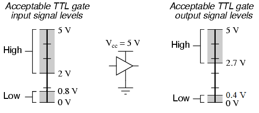
This is incorrect. 0.8V was the upper limit of low, and 0V was used to denote low.
"Nowadays, a 'high' is 0.75 V and a 'low' is around 0.23 V. He added
that in the near future, we may shift to a system where 0.4 V denotes
a high, and 0.05 V, a low."
Again, this is incorrect. Zero is still logic low. Although there are a range of values that can also be interpreted by the hardware as logic low, zero is still logic low.
"He argued that these values are getting smaller so that we can reduce
our power consumption."
This is partially correct. It is the DIFFERENCE between these values that is getting smaller so that we can reduce our power consumption.
The choice of high and low voltage are, technically, arbitrary. They are standardized for obvious reasons. Throughout the history of electronic circuits, there have been many, many, many other high and low voltage levels used than the ones you stated, and many with a logic high far higher than +5V and logic lows far lower than 0V!
Why don't we just set it to the true 0 V
We do. We absolutely do set it to true, absolute, exactly 0V by specification, very often in fact. However, we also build in a range of values because very often, we find it difficult to reach absolute 0V for the reasons stated by the other posters.
You can't make the difference between the low and high voltages zero for obvious reasons (how would you tell the difference between the two?)
The fact of the matter is that the voltage is only part of the equation when it comes to power consumption. The power used by the logic circuitry is much more important, and voltage is merely one part. You could have a theoretical +5V High, 0V Low circuit that draws far less power than a +1V High, 0V low circuit.
It turns out that there are fundamental, universal limits to the minimum amount of power any logic circuit can draw, regardless of how you design it. Look up reversible computing theory.


