I am doing a two-stages amplifier for a very small signal (-+300uV), coming from a radar sensor.
The following two images are taken from application notes.
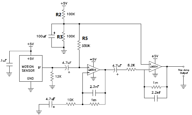
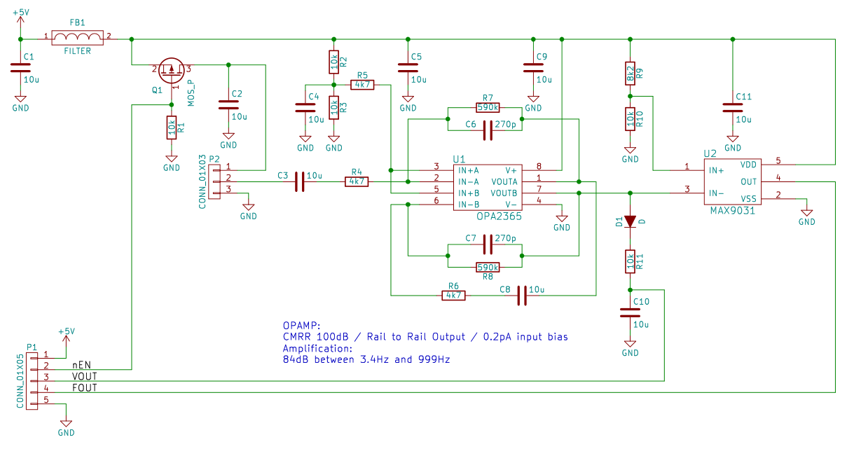
I know R2 and R3 are voltage divider. 2.5V is required to shift the input signal.
What is the purpose of R5 in both circuits?
Why is it not used in stage 2 at the amplifier A and used in both stages at the amplifier B?
Is it a current limiter? If so, who can I design its value?
Also note that I have applied the amplifier B with LM358 instead of OPA2365 and I sensed a very weak (micro Volt) periodic (10 Hz) oscillated signal and I did not see that at amplifier A. and the difference is clearly the first stage (inverting and non-inverting).
However, the main question is: what are R5 doing?


