0
\$\begingroup\$

I wanted a 16V,50A regulated power supply but could not find it in the market. I also searched for a buck converter for the same current output and could not find anything. So I thought of making it with a high current (60A) motor driver and a 45V, 20A SMPS. However, upon checking the output signal of the motor driver, I found out that it is actually a PWM signal (amplitude: 45V, frequency: 16KHz) and here lies my problem. Since I have a load which can take a maximum of 17V DC at input, connecting my motor driver directly to it is not a good idea. Now I am looking for ways to convert (or filter) this PWM output into an constant DC voltage (depending upon the duty cycle of PWM obviously!) so as to feed it into my load.

Could anyone please help me with the filter/converter design? I read about low-pass RC filters but given the amount of current that I am drawing, I will need an insanely small value of resistance with a high power dissipation capacity (about 800W) and also a very large value of capacitance (which makes it impractical.)

A rough schematic of my arrangement looks something like this:

schematic

simulate this circuit – Schematic created using CircuitLab

On a side note, my load is expected to draw 40A current at 16V and I understand that I will need feedback to regulate my output voltage.

\$\endgroup\$
7
  • \$\begingroup\$ IF you did what you say then a buck converter is what you'd want. Input the PWM into an LC filter (NOT RC) , add a freewheel diode at the inductor input to ground, and Bob's your uncle. Unfortunately, that's a humungous first buck converter to build and the chances of smoke flame pain tears and just maybe injury or death are not low enough. || SO instead of asking us how to do something semi-random to so;ve your problem, why not tell us what you actually want to do and see how we can help. This usually works out MUCH better. ... \$\endgroup\$
    – Russell McMahon
    Commented Nov 6, 2019 at 7:38
  • 1
    \$\begingroup\$ |Why 16V 50A? what is the application, fixed Vout or variable over what range, what accuracy and load variability and ...? || What made you start with 45V. Why not 18V or 20V or ... . " The company "Meanwell" make reasonably capable psus at reasonably OK prices. You could check their range,. Several in parallel may be sensible. Or not. \$\endgroup\$
    – Russell McMahon
    Commented Nov 6, 2019 at 7:38
  • \$\begingroup\$ Firstly, i am making a power system for a tethered drone. My motor and ESCs are rate for 4S or 16.8V max. Second, paralleling power supplies will need them to be synchronized externally, which might be as easy as my approach. What do you think? \$\endgroup\$ Commented Nov 6, 2019 at 7:55
  • \$\begingroup\$ " i am making a power system for a tethered drone" a 'tethered drone'? Why??? \$\endgroup\$ Commented Nov 6, 2019 at 8:13
  • \$\begingroup\$ Hi Bruce, the answer is because I want to test my algorithms and all possible variations which can take a couple of hours at least, I don't think battery will give me more than 1/2 hour of flight time. Also, cannot have too many batteries and chargers...Seems like a lot of work. Can powering a drone with proper SMPS cause any problems? \$\endgroup\$ Commented Nov 6, 2019 at 8:36

2 Answers 2

1
\$\begingroup\$

I found out that it is actually a PWM signal (Amplitude : 45V, freq: 16KHz) and here lies my problem.

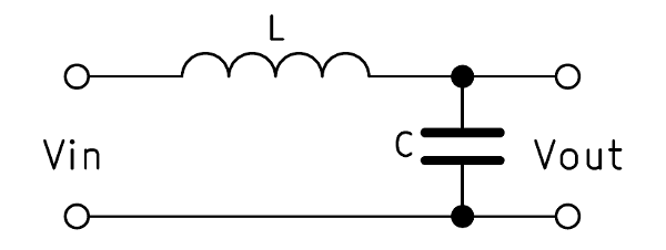
You need an LC low pass filter with a cut-off frequency of a few kHz and moderate Q value: -

enter image description here

The cut-off frequency is defined by the equation: -

$$F_c = \dfrac{1}{2\pi\sqrt{LC}}$$

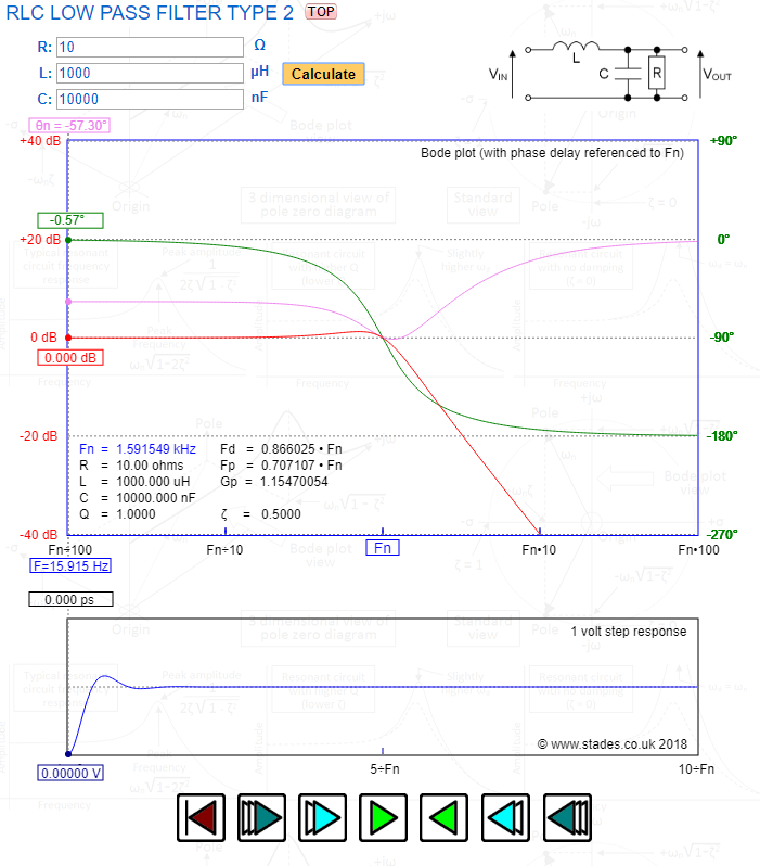
Use this filer calculator to experiment with suitable values: -

enter image description here

I've made a head start for you with values for L of 1 mH and C of 10 uF but be aware that the filter can produce large resonant peaks if the load is removed (R) and this is the reason for making the cut-off frequency significantly below 16 kHz.

I would also recommend an output monitoring circuit that can switch off the controller should the DC output rise above some top-limit.

\$\endgroup\$
2
  • \$\begingroup\$ Hi Andy! Thank you for your answer. I have a doubt : Won't there be a voltage drop across the 100 ohm resistor in the filter itself? \$\endgroup\$ Commented Nov 6, 2019 at 8:43
  • \$\begingroup\$ There is a 10 ohm resistor in my answer but that is the load resistor. \$\endgroup\$
    – Andy aka
    Commented Nov 6, 2019 at 9:53
3
\$\begingroup\$

This seems like a case of the XY problem. I think you would be better served asking for what you really want, a 16V 50A supply for a tethered drone, rather than asking for how to adapt an entirely unsuited PWM motor controller to the task of supplying a constant voltage.

An LC filter will only work when the PWM driving it is symmetrical. IE, it must source and sink equal current. If it only sources current, the output from an LC filter will be highly nonlinear, in fact it will look like an exponential charge curve. And a fixed PWM through an LC filter will yield a voltage that changes with load.

16V @ 50A is 800W. So give the power supply some headroom, and relax the restriction on voltage because LiIon cells drop during use anyway...

Mean Well sells a 15Vdc 1kW 66.7A output switch mode power supply, the SE-1000-15. Mouser Electronics sells it for about $170 USD. Short circuit and overload protection.

Here is the datasheet: Mean Well SE-1000-15

\$\endgroup\$

Your Answer

By clicking “Post Your Answer”, you agree to our terms of service and acknowledge you have read our privacy policy.

Not the answer you're looking for? Browse other questions tagged or ask your own question.