2
\$\begingroup\$

I have designed a board with the ICM-20789, but am having trouble keeping stable voltage values on the I2C bus. Datasheet

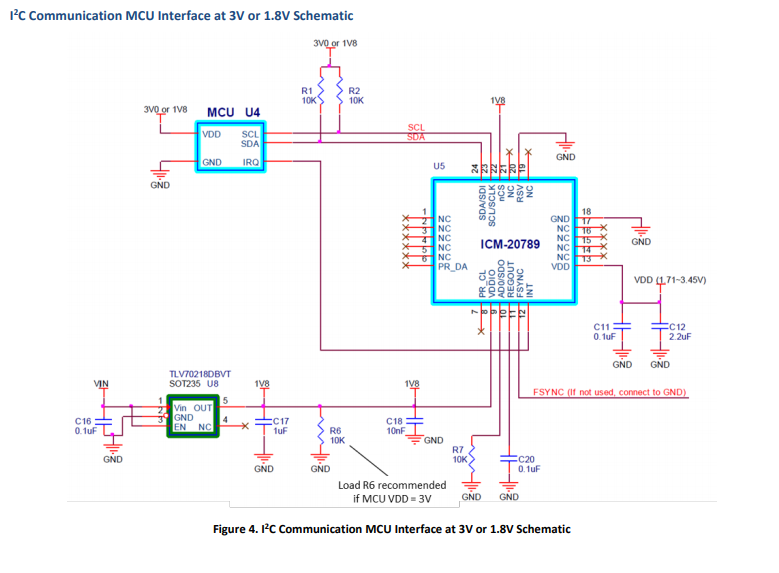
I have followed the schematic that was listed inside the datasheet, and that is pictured below. I have a 5V ATMega32u4 that is acting as the master and for this reason, I wanted to run the device at 3.3V logic on I2C.

enter image description here

I have listed my schematic and board layout below as well. enter image description here
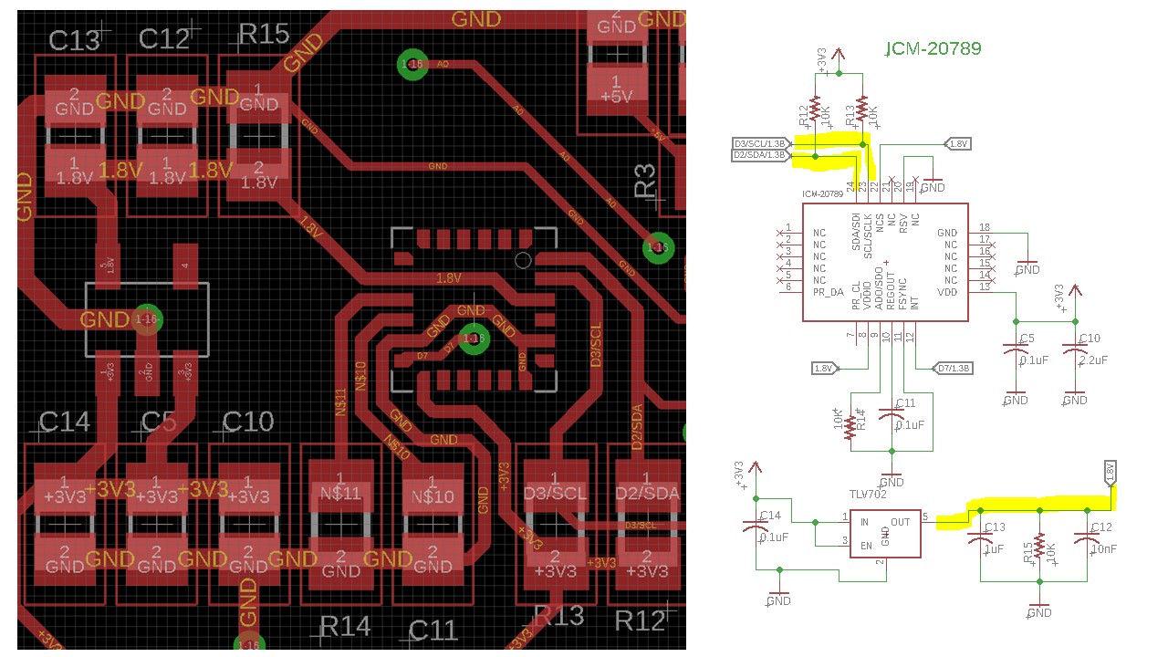
The issue I am having is with the I2C bus and 1.8V line not being the correct voltage. (The lines I am referring to are highlighted in my schematic.)

When using 10K pullup resistors for the I2C line and a 10K resistor for R6 in the datasheet and R15 in my schematic, the voltage regulator runs at a perfect 1.8V, but the I2C lines are running at 2.5V, to low for the ATMega32u4 to read as a logic high. (3.0V when running at 5V).

When I replace the I2C pullup resistors with a 4.7K resistor, then the voltage I2C lines run at above 3V, but the 1.8V is now at 2.1V.

I then trying using 4.7K resistors on the I2C bus, and a 1K resistor for the pull down on the regulator. Again, I have the issue where the regulator gives a perfect 1.8V, but the I2C voltage is to low.

It appears the schematic is saying that it is possible to run the device at 3.3V logic, but I cannot seem to get it working. Any ideas as to why this is happening and how to fix it would be greatly appreciated!

\$\endgroup\$
2
  • \$\begingroup\$ how are you measuring the voltage? scope? DVM? where is the scope probe ground (that 6" lead with the alligator clip at the end) connected? \$\endgroup\$ Commented Nov 23, 2019 at 9:23
  • \$\begingroup\$ @analogsystemsrf I am using both a DVM and oscilloscope to measure the voltages. The I2C line is not sending any information when I am taking the measurements so the line is left high. I have measured at many different ground points across the board. \$\endgroup\$ Commented Nov 23, 2019 at 22:10

1 Answer 1

2
\$\begingroup\$

It's possible there is an error in the datasheet and the SCL/SDA and INT pins should not be pulled above VDDIO because of protection diodes. That would exactly explain the symptoms you are seeing. The datasheet refers to pullups to VDDIO (which, as you know, is limited to about 2V) in several places.

I suggest you contact the manufacturer and confirm. To get this to work, assuming I'm right, you'll have to add voltage translators such as the PCA9306 between the MCU and the chip, as shown in the schematic Figure 7. The INT line will also need voltage translation.

\$\endgroup\$
2
  • 1
    \$\begingroup\$ I was scared that it was a mistake in the datasheet. On page 34 of the datasheet, it states "The ICM-20789 supports I2C communications on its serial interface. The ICM-20789’s I/O logic levels are set to be VDDIO" It also shows a simplified schematic that appears to contradict the schematic that I have posted. So without a level shifter, the device cannot have I/O level of 3.3V? \$\endgroup\$ Commented Nov 23, 2019 at 22:13
  • 1
    \$\begingroup\$ That's my best guess. I don't see anything that exactly confirms it (logic levels could still be Vddio with it being 3.3V tolerant) , but the error theory fits your observations and it's hard to imagine what else would cause that. \$\endgroup\$ Commented Nov 23, 2019 at 22:33

Your Answer

By clicking “Post Your Answer”, you agree to our terms of service and acknowledge you have read our privacy policy.

Not the answer you're looking for? Browse other questions tagged or ask your own question.