2
\$\begingroup\$

I have redesigned one of my boards to the ICM-20689 (datasheet) instead of the ICM-20789 because of a voltage issue that I previously had. Link to previous issue.

A little background on my setup. The ICM-20689 is running on 3.3V with 3.3V on the VDDIO pin and 10k pullup resistors on the I2C bus. The master device is running at 5V, but only needs 60% (3V) to read a voltage high. The frequency is set to 400kHz.

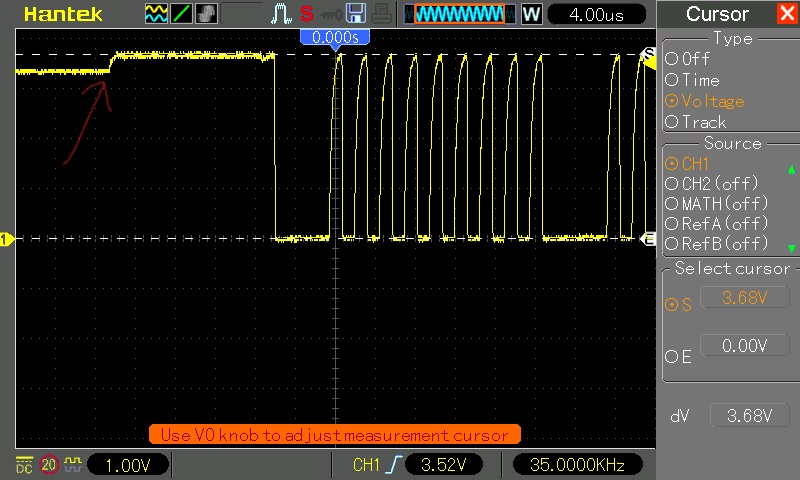
I have been able to communicate with the device just fine and get good data. I wanted to look at the bus voltages with an oscilloscope to make sure that everything looked fine, and I noticed something a little odd. Before the master starts talking with the ICM-20689, the bus line is at a voltage of 3.3V. When the master wakes up the device and starts receiving data, the voltage jumps to 3.7V.

enter image description here

My oscilloscope is not the greatest, but the probe is in 10x mode, and I am using the trigger to capture the data on the first packet of data sent. On all subsequent data packages, the voltage stays at 3.7V. Is this is an issue with the device, or is this maybe an issue with my measurement setup?

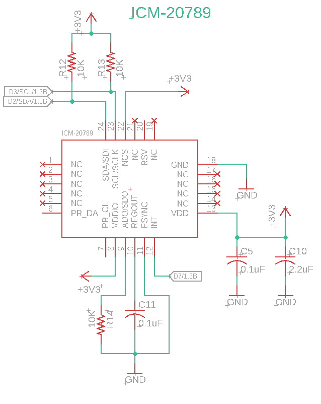
Edit: Here is the schematic for the ICM-20689. This "voltage bump" happens on both the SCL and SDA lines. To my knowledge, there are no internal pull-ups active on any devices on the bus.

enter image description here

Is this normal for I2C? What is causing this bump? Is this something I should be worried about, or is this within allowable tolerances?

\$\endgroup\$
5
  • 2
    \$\begingroup\$ Can you share your schematic? What voltage are the I2C pull-ups connected to? Do any of the ICs on the bus have internal pull-ups? To what voltages? \$\endgroup\$
    – The Photon
    Commented Apr 28, 2020 at 0:39
  • \$\begingroup\$ "The master device is running at 5V, but only needs 60% (3V) to read a voltage high." - What device is the master? (can't be an ATmega32u4, because that needs 0.7*Vcc = 3.5V). \$\endgroup\$ Commented Apr 28, 2020 at 1:08
  • \$\begingroup\$ The voltage is consistent with extra ~30k pullup to +5V. ATmega32U4 has internal pullups 20-50k that can be enabled on I2C. Show us your code. \$\endgroup\$ Commented Apr 28, 2020 at 1:19
  • \$\begingroup\$ @BruceAbbott It is indeed the ATMega32u4, though looking at the datasheet, it is indeed 0.7, not 0.6. I am using the standard "Wire.h" library for Arduino, and call Wire.begin(); in the setup. I assumed this would not be activating pull-up resistors but I appear to wrong yet again! I have been using 3.3V devices with this chip for years and haven't seemed to have a problem yet, even though I am below specification. \$\endgroup\$ Commented Apr 28, 2020 at 1:47
  • \$\begingroup\$ Well the extra pullup is getting the voltage over 3.5V, so you're all good! (apart from exceeding the sensor chip's rating). I have a commercial device with an I2C sensor that failed intermittently due to a mismatch like this (3.3V sensor, 5V MCU with pullups to 5V). Injected current eventually blew up the sensor chip! \$\endgroup\$ Commented Apr 28, 2020 at 2:25

1 Answer 1

3
\$\begingroup\$

In the comments you say that you are using an ATmega32U4 with the standard Arduino Wire library. Pullup resistor value for that MCU is specified as 20 - 50k Ω. A value of ~32k would cause the voltage you are seeing.

In twi.c we see:-

void twi_init(void)
{
  ...

  // activate internal pullups for twi.
  digitalWrite(SDA, 1);
  digitalWrite(SCL, 1);

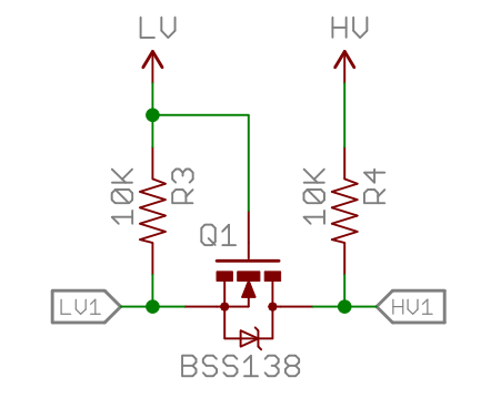
To disable the internal pullups you could comment out those lines in the library code. However then you may have problems with the voltage being too low for reliable operation (ATmega32U4 specifies minimum high level of 0.7 * Vcc, which is 3.5 V at Vcc = 5 V). The proper solution is to use an I2C level shifter circuit like this:-

enter image description here

\$\endgroup\$

Your Answer

By clicking “Post Your Answer”, you agree to our terms of service and acknowledge you have read our privacy policy.

Not the answer you're looking for? Browse other questions tagged or ask your own question.