1
\$\begingroup\$

I am currently designing a BLDC controller and keep running into a power safety issue:
I have added a smart diode reverse protection controller to my design with its transistor between the fuse and the bulk capacitance (4 x 220uF elcap bank).
This was done to protect all downstream components (and the polarized capacitors especially) from reverse polarity events. Now obviously this poses a big problem during regenerative braking since the IC (LM5050) interrupts the supply line and makes the micro think an undervoltage event occured (which it momentarily did, since the power to the motor was cut).

What is a good way to mitigate/solve this issue and how does this get solved by real electronics designers?
Thanks!
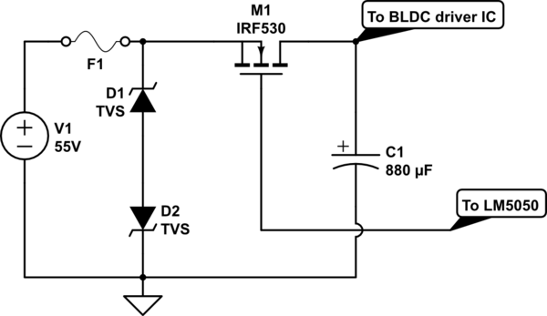
schematic

simulate this circuit – Schematic created using CircuitLab

\$\endgroup\$
6
  • \$\begingroup\$ now obviously this poses a big problem during regenerative braking Do you think this will be an issue or is it a fact (like the IRF530 blew up due to regenerative braking)? \$\endgroup\$
    – Huisman
    Commented Dec 3, 2019 at 11:00
  • \$\begingroup\$ @Huisman it is an issue. \$\endgroup\$
    – Alex Er
    Commented Dec 3, 2019 at 14:54
  • \$\begingroup\$ Is it your intent to feed the energy produced by regen braking pack into the power supply? Hopefully this is a battery or supercap capable of absorbing the current without an excessive rise in voltage. If so, the LM5050 is bound to shut off to prevent the reverse current, so it's not the solution you need. The simpler voltage-based protection in the answer is what I have used. \$\endgroup\$
    – Phil G
    Commented Dec 3, 2019 at 15:24
  • \$\begingroup\$ consider just using a polarized battery connector instead \$\endgroup\$
    – DKNguyen
    Commented Dec 3, 2019 at 15:52
  • \$\begingroup\$ @PhilG yes, that's what I'm trying to do and yes, that's what's happening. Did you use a FET with it's drain pin to the negative battery terminal, source to pcb gnd and gate to the positive battery terminal? If so, does this work well? \$\endgroup\$
    – Alex Er
    Commented Dec 3, 2019 at 15:52

3 Answers 3

2
\$\begingroup\$

If you only want to protect against reverse polarity then you are using the wrong technique. Instead of an LM5050 you can just turn the FET on with positive supply voltage. If the polarity is reversed the FET won't turn on.

schematic

simulate this circuit – Schematic created using CircuitLab
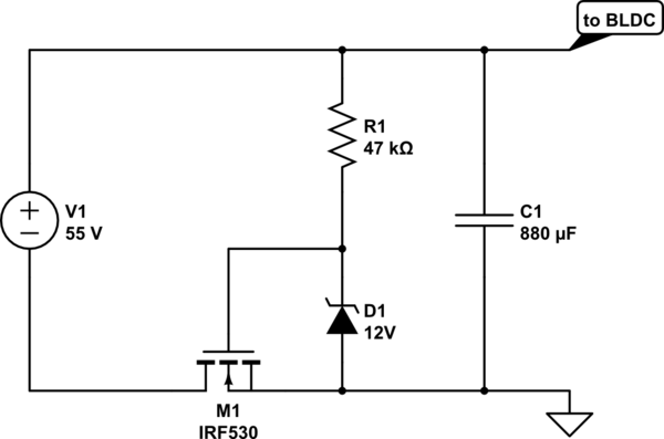
As in your circuit the FET is oriented so the body diode conducts, then the FET shorts it out when turned on. However since we don't have a Gate voltage booster the FET has to placed in the negative lead so positive supply voltage will turn it on. This means either the supply or controller's negative rail must be floating (not connected to ground).

\$\endgroup\$
5
  • \$\begingroup\$ The sensing and GND pins of the LM are isolated from the device ground. IMO this is not an incorrect technique as the IC has a gate driver, and sense input for rpp. The body diode doesn't really matter as it only conducts when everything is polarized correctly. When conduction occurs the internal comporator of the LM5050 checks the difference between drain and source and drives the gate if all is ok. \$\endgroup\$
    – Alex Er
    Commented Dec 3, 2019 at 14:59
  • \$\begingroup\$ Using a high side gate driver for this 'works' but is over-engineering IMO for a feature with debatable value. Plus, I think either of the posted alternatives should fix your undervoltage issue \$\endgroup\$
    – Ocanath
    Commented Dec 3, 2019 at 18:13
  • \$\begingroup\$ Perhaps I didn't make it clear enough. You don't want an ideal diode (which prevents reverse current flow during regeneration), but a device that only blocks negative power supply polarity. I don't think the LM5050 can do that. \$\endgroup\$ Commented Dec 3, 2019 at 23:47
  • \$\begingroup\$ @BruceAbbott that's a good sollution, I think i was really too fixated on an integrated sollution and overthinking things with this LM5050. I appreciate the simplicty. Thank you very much! \$\endgroup\$
    – Alex Er
    Commented Dec 4, 2019 at 10:51
  • \$\begingroup\$ @Ocanath yes, agreed. I was really too fixated on an integrated sollution and overthinking things with this LM5050. I appreciate the simplicty. Thank you very much! \$\endgroup\$
    – Alex Er
    Commented Dec 4, 2019 at 10:51
1
\$\begingroup\$

If you're committed to using an N-MOS, the configuration in Bruce's answer is what you want. I just wanted to add that if you had a particular reason to want to put your reverse protection in the power path, you can alternatively do the following (using a PMOS)

schematic

simulate this circuit – Schematic created using CircuitLab
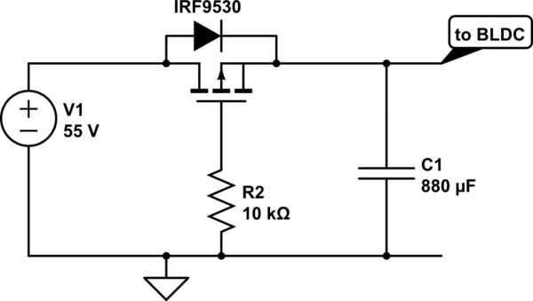
\$\endgroup\$
0
0
\$\begingroup\$

Brother, you are using 2 mosfet for one phase. And total are 6 mosfet Q1 TO Q6. let us suppose Q1 and Q2 IS Controlling one phase A. There is diod fron drain to sourse. And a resistance is fron sourse to gate. A capistor ia attached between 2 mosfet Q1 and q2. A diod is also attached to the center tap of Q1 and Q2. Now you connect your gate driver with mosfet gate through a resistor. Your one phase is ready with full bootstrap circuit’s. Free wheeling diod is already place

\$\endgroup\$

Your Answer

By clicking “Post Your Answer”, you agree to our terms of service and acknowledge you have read our privacy policy.

Not the answer you're looking for? Browse other questions tagged or ask your own question.