0
\$\begingroup\$

I am building a gauge to replace another in my instrument cluster. I am adding some LEDs and an OLED screen and I would like them to have adjustable dim with the old incandescent backlight bulbs. I plan on using a voltage divider and low pass filter, as well as averaging the ADC value to compensate for voltage swings as the alternator, alternates? (programmed to vary voltage pretty widely in operation)

My car has a low side switch for controlling the dimming, that is all bulbs are directly connected to the +12V headlight/indicator relay/fuse, all then go to the dimmer switch which has an oscillator and some sort of switch, also powered by the +12V from indicator fuse.

If I am not mistaken, if I measure the lead before the PWM switch and pass it through a low pass filter I should get a voltage, right? If the dimmer is at minimum pulse width, minimum brightness, I would expect to read nearly 12V, and if the dimmer was at full brightness I would expect to read much lower voltage, pretty much the resistance of the PWM switch times total circuit current? (was also hoping to use this ADC to detect when the headlights are on!)

I have attached a schematic of my dimmer circuit. The wire I think I should measure is GY/R

https://i.imgur.com/CmVimBO.png

Thank you in advance for any advice!

Edit: I went ahead and measured the frequency and duty cycle of the dimmer, it varies from 60Hz 1%DC at minimum dim, and maxes out at 100hz and 80%DC.

I am trying to cram this all in place of a factory gauge, I can't really fit any easily available opamps. Instead, I plan on using a rail to rail opamp.

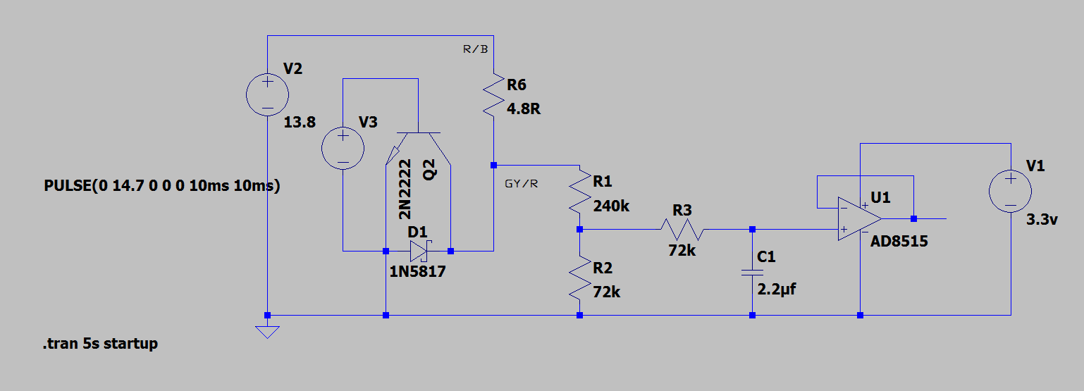
Here is my proposed schematic, the response time is slow, but not so slow to be unmanageable for this application. The high impedance of the divider circuit and opamp input should keep any ground leakage to a minimum when the lights are fully dimmed. The divider is set for a maximum of 14.7, and I plan on letting the opamp manage any extra overvoltage from there. The divider circuit and RC should limit current to a level the internal clamp diodes should handle.

Thank you for the advise!

enter image description here

\$\endgroup\$

2 Answers 2

1
\$\begingroup\$

You are getting a PWM signal why are you going to an analog version. PWM works with LEDs and tungsten filament lamps. Analog is not good for LED control. You could use a few transistors to amplify the signal drive while still maintaining 12V power. I have seen it done this way in OEM instrument clusters. The PWM comes into a small BJT that then drives the output MOSFET or Transistor. This would be much simpler, smaller and more more cost effective. Many places in a lot of the forums you can find where they use a low pass filter with pwm to do a D/A converter. Essentially that is what your voltage measurements as the circuit has a lot of capacitance. In your design remember you will be working with system voltages that can range from 6V to 24V and the potential of reverse battery (double battery jump connected backwards).

\$\endgroup\$
0
\$\begingroup\$

Your analysis of the operation is correct but I would be concerned that the output of your averaging filter would vary quite a bit with engine revs since the '12 V' will vary with engine revs, etc.

schematic

simulate this circuit – Schematic created using CircuitLab

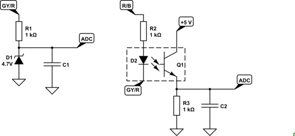
Figure 1. A couple of options.

The circuit on the left is a simple Zener clamp which, without C1, gives a 4.7 V PWM signal independent of the actual 12 V supply voltage. The R1 / C1 values will have to be selected to suit the oscillator frequency.

The circuit on the right does the same thing but opto-isolates the PWM signal from the micro-controller.

Getting the low-pass filter right is your biggest challenge and it may get a bit more complicated than I've shown it here.

\$\endgroup\$
6
  • \$\begingroup\$ Thank you for the reply! I will use a pocket scope to measure the frequency of the oscillator. From there I think I can futz about with LTspice/google to figure out the RC values. I had planned on using a resistor divider and rail to rail opamp on the input, just to make sure I don't blow anything up. I sized the divider for a decent amount of overvoltage, and I can read battery voltage to apply compensation over CAN. Otherwise I might need to find smaller optoisolators... Thank you again! \$\endgroup\$
    – Deezums
    Commented Dec 4, 2019 at 8:13
  • \$\begingroup\$ Actually, thinking on it more I really like the idea of using an optoisolator. I should be able to prevent any stray leakage to ground, especially when the lights are fully dimmed. Thank you again for the advise! \$\endgroup\$
    – Deezums
    Commented Dec 4, 2019 at 8:24
  • \$\begingroup\$ I forgot to point out in the answer that the opto-solution also allows increasing analog with increase in pulse width. Why not just power your OLEDs with a repeat of the PWM from the opto-isolator? No analog stuff! \$\endgroup\$
    – Transistor
    Commented Dec 4, 2019 at 8:28
  • \$\begingroup\$ Thank you again! Inverting the signal would be a nice benefit! My LEDs are the digital RGB type, and the OLED is a 128*128 flat panel. I guess I could measure frequency or duty cycle and convert that to values easy to translate to the 8 bit brightness they understand. Assuming I can't find an optoiso that fits, I can instead use a NPN between R/B and GY/R right? I assume so, it works for the rest of my ECU! So far I haven't found anything else that fits! i.sstatic.net/IwkoR.gif \$\endgroup\$
    – Deezums
    Commented Dec 4, 2019 at 20:05
  • \$\begingroup\$ Post a schematic of your latest plan into an edit of your question. You can add one in using the CircuitLab button on the editor toolbar. Double-click a component to edit its properties. 'R' = rotate, 'H' = horizontal flip. 'V' = vertical flip. Note that when you use the CircuitLab button on the editor toolbar and "Save and Insert" on the editor an editable schematic is saved in your post. That makes it easy for us to copy and edit in our answers. You don't need a CircuitLab account, no screengrabs, no image uploads, no background grid. \$\endgroup\$
    – Transistor
    Commented Dec 4, 2019 at 20:26

Your Answer

By clicking “Post Your Answer”, you agree to our terms of service and acknowledge you have read our privacy policy.

Not the answer you're looking for? Browse other questions tagged or ask your own question.