0
\$\begingroup\$

I'm trying to model a differential digital signal going through 4000 feet of twisted shielded pair. The nominal impedance is 120 ohms and capacitance per foot is 14.6 pF.

For 1000 feet I calculated the inductance should be .0002 H and 14600 pF. I broke the model up into 4 segments. Each one with 14600 pf cap, and .0001 Henries on each wire. I put four of these together with a 120 ohm resistor termination.

The results look close but not exactly what I see in reality. The pulse width is really wide compared to what it should be and the output is ringing more than it should.

How many segments is enough to break 4000 feet into? 10? 100? Is there anything else I can do differently?

\$\endgroup\$
1
  • \$\begingroup\$ You highest signal frequency was a wavelength and each lump should not be more than representing a distance of one tenth of that wavelength. \$\endgroup\$
    – Andy aka
    Commented Dec 24, 2019 at 8:24

2 Answers 2

1
\$\begingroup\$

For 1000 feet I calculated the inductance should be .0002 H and 14600 pF. I broke the model up into 4 segments. Each one with 14600 pf cap, and .0001 Henries on each wire.

If you broke it up into 4 segments, then each segment should have 3650 pF and 0.00005 H.

Despite what the other answer said, this is a perfectly reasonable way to solve this problem, and essentially the same as what Spice would do under the hood if it you used a Spice that had built-in transmission line models.

How many segments is enough to break 4000 feet into? 10? 100?

The usual way to work this out is to first try 10, then 20. If the answer didn't change, then 20 is enough. If the answer changed, then keep increasing the number of segments until the results stop changing.

\$\endgroup\$
0
\$\begingroup\$

Sounds like you're trying to analyze this as a lumped sum model, or a series of lumped sum models. That is not adequate for your scenario. While you didn't mention what your operating frequency is, I'll bet it's high enough that you need to treat the 4000 feet of TSP as a transmission line.

It's also helpful to know what your electrical interface is, RS-422/485, LVDS, something else?

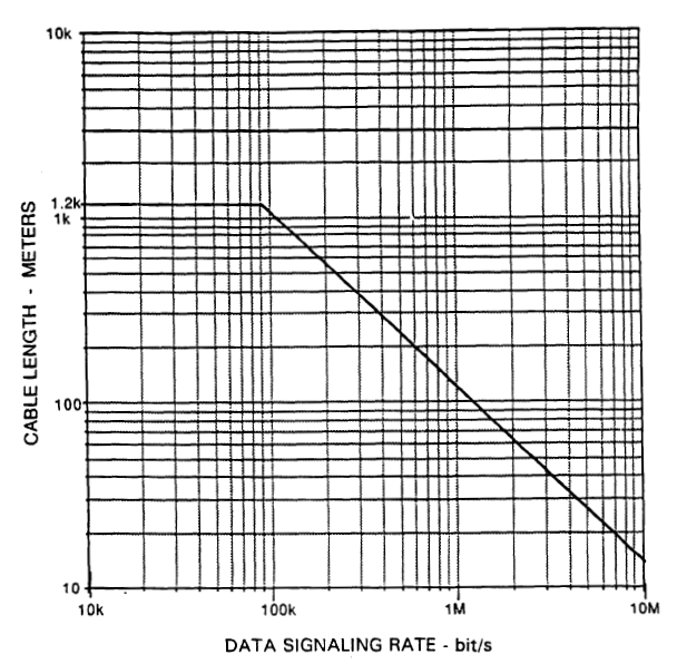
The '422 specifications (now kept by TIA-EIA, I believe) has the following chart in it that relates signaling rate to cable length: enter image description here Image from ANSI/TIA/EIA-422-B-1994.

\$\endgroup\$
1
  • \$\begingroup\$ Breaking up a transmission line into L or Pi or T sections is exactly how a simulator would solve this problem if you used a simulator with built in transmission line modelling. It's essentially just doing a simplified FEM appropriate for a problem with uniform geometry along the transmission line. \$\endgroup\$
    – The Photon
    Commented Dec 24, 2019 at 2:34

Your Answer

By clicking “Post Your Answer”, you agree to our terms of service and acknowledge you have read our privacy policy.

Not the answer you're looking for? Browse other questions tagged or ask your own question.