0
\$\begingroup\$

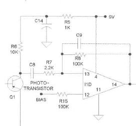
In the following picture:

enter image description here

I have screenshotted a picture of the front end of a phototransistor receiver circuit from Electronic Gadgets for the Evil Genius. It appears to be a phototransistor-based transimpedance amplifier. However, I am having trouble understanding the relationship between the phototransistor's collector current and the output of the amplifier, I1D.

How would I determine the relationship between the collector current and Vout in this circuit? And how would I convert this circuit to a photodiode-based amplifier? Would this improve the signal-to-noise ratio?

I've looked at a few application notes, but what am I missing?

In this circuit, C8 = 0.01 uF and C9 = 470 pF.

\$\endgroup\$
2
  • \$\begingroup\$ I remember using phototransistors for a papertape reader. They work okay when turning light into digital signals. But cripes, I cannot remember coming across phototransistors since... well, maybe the early 1980s? I have a box of them. But I bought them in the mid 1970s! Does anyone use them for linear amplification? Photodiodes are usually much better. (Just mumbling to myself out loud.) \$\endgroup\$
    – jonk
    Commented Dec 26, 2019 at 4:45
  • \$\begingroup\$ It would be easier to give suggestions for converting to a photodiode if you explained what you were hoping to improve. \$\endgroup\$ Commented Dec 26, 2019 at 7:06

2 Answers 2

4
\$\begingroup\$

Actually, that is not a TIA. It's a fairly simple AC amplifier with a gain of about 45 (100k / 2.2k).

I presume the emitter of Q1 is tied to ground. Then the voltage at the collector will be 10k times the current in amps. DC levels (or at least, fairly low frequencies) will be blocked by C8. For frequencies above that set by R7/C8, and below that set by R6/C9, the gain of the amp will be the aforementioned 45.

This will be complicated by the fact that R7 is only about 1/4 R6. This means that for a given current variation in Q1, the effective value of R6 will be about 1/4 of what you'd expect, since R7 will tend to shunt away most of the current. So the effective gain will be more along the lines of 11 or 12, rather than 45.

\$\endgroup\$
2
  • \$\begingroup\$ Obviously, the non-inverting configuration is more appropriate here... \$\endgroup\$ Commented Dec 27, 2019 at 6:21
  • \$\begingroup\$ @Circuitfantasist - Nope. That's what the bias voltage is for. For a 9-volt supply, maximum output AC swing will occur with VBIAS set to 4.5 volts, although this may not be appropriate for an unknown load. However, since the op amp only responds to AC signals, an output coupling capacitor is probably a good idea. \$\endgroup\$ Commented Dec 29, 2019 at 2:42
0
\$\begingroup\$

And how would I convert this circuit to a photodiode-based amplifier?

It would depend on what you were trying to do, but probably you would reverse bias your photodiode and remove R6 and R7. A basic transimpedance amp for a biased photodiode is just the bias voltage, the diode and the amplifier with it's feedback network. It is even more simple than what you have.

Would this improve the signal-to-noise ratio?

It's impossible to answer this without a lot more information. Generally photodiodes are the best detector to use when you have enough photons over your detection interval that your electronic noise is well below the smallest number of photons you want to detect. As you have less and less light, detectors with gain are needed to raise the signal above the electronic noise floor. A phototransistor is a very cheap (if not the highest performing) way to get gain out of your detectors. The downside is that their bandwidth is very low, and the gain process is noisy (each individual photon generates a variable number of electrons). If you have a bright signal and you feed it into a phototransistor, you may find that the largest noise source in the circuit is the gain noise in the transistor. In that case, a photodiode will work better. If you have a week signal, you may not be able to build a practical transimpedance amp that gives a low enough noise floor for a photodiode to work well.

\$\endgroup\$

Your Answer

By clicking “Post Your Answer”, you agree to our terms of service and acknowledge you have read our privacy policy.