0
\$\begingroup\$

I'm making a HID keyboard which connects through micro-usb. Unfortunately I made an error in the PCB design and missed including a slot for the usb connector to fit in.

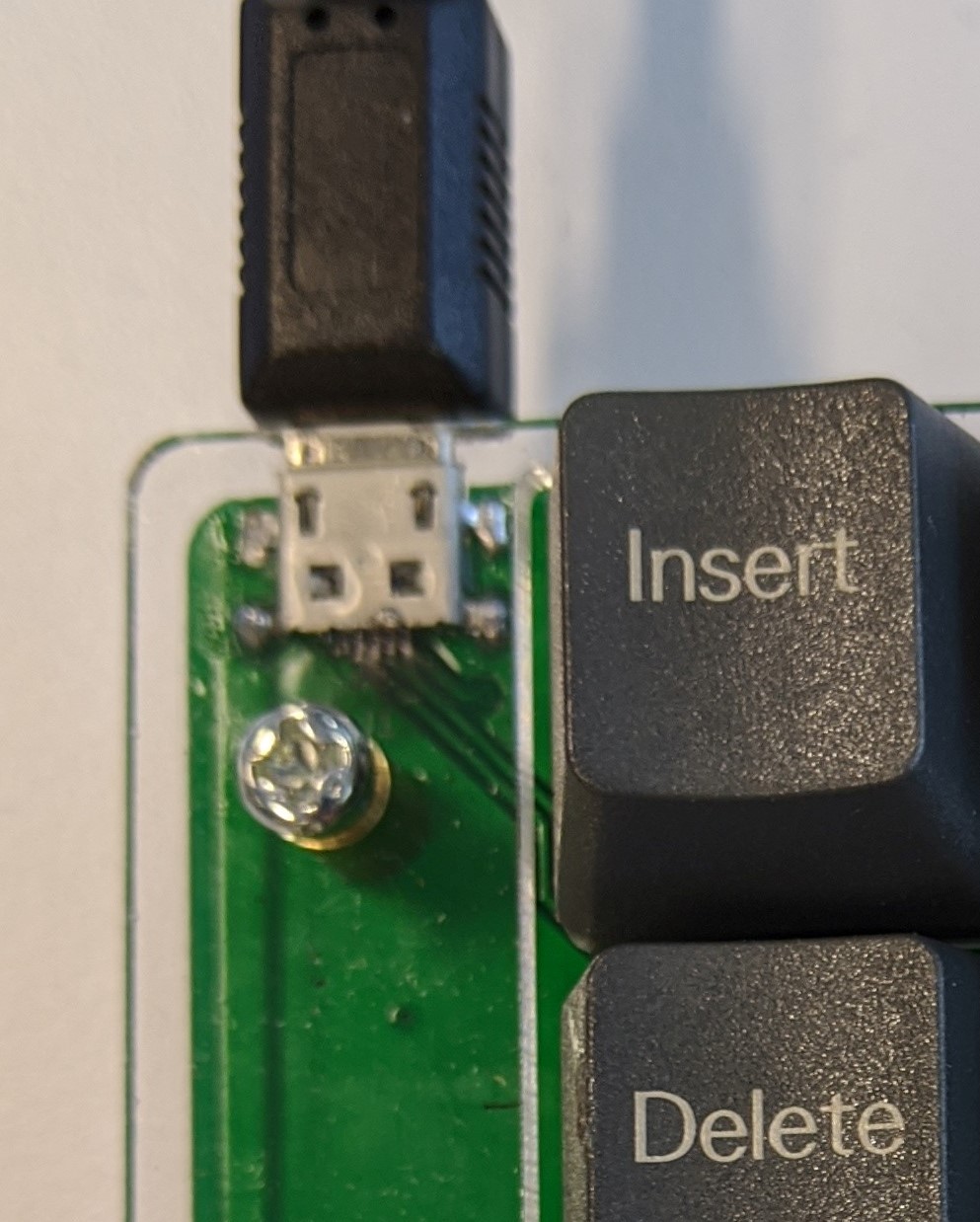
Being the enterprising DIY hacker that I am, I used a hand file, like this one, to cut out the slot and then house the USB connector snugly within it. Here's an image of the finished connector:

enter image description here

I assembled 2 boards and both of them have weird connectivity issues with the device working sometimes, but most times just failing as a malfunction.

The USB port's outer housing is grounded. My question is, is it possible that by filing, I exposed the ground plane and the VDD plane and now the USB connector is shorting with it, thus causing the device malfunction?

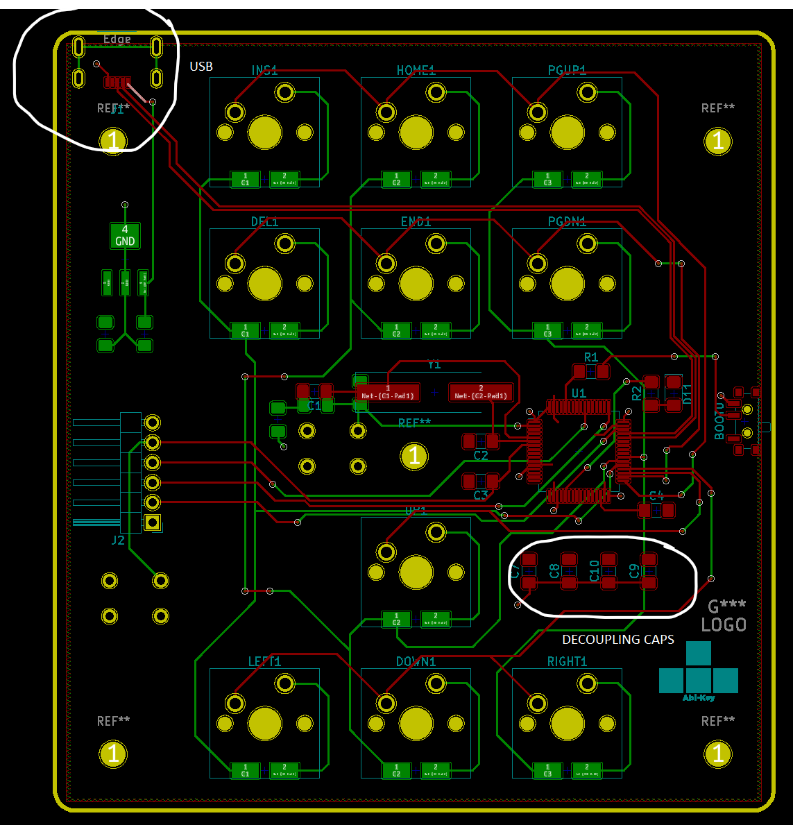
EDIT: Here's an image of the PCB layout. Have marked the USB port and the De-coupling caps.

enter image description here

\$\endgroup\$
17
  • \$\begingroup\$ Get a DVM and prove your theory. \$\endgroup\$
    – Andy aka
    Commented Jan 3, 2020 at 11:23
  • \$\begingroup\$ @Andyaka - Whats a DVM? Voltmeter? \$\endgroup\$ Commented Jan 3, 2020 at 11:29
  • \$\begingroup\$ Digital volt meter. \$\endgroup\$
    – Andy aka
    Commented Jan 3, 2020 at 11:36
  • 2
    \$\begingroup\$ Would it be difficult to unsolder the 4 connections to the outer housing? Best try and fix what you have rather than carry an unforeseen error to a new design. \$\endgroup\$
    – Andy aka
    Commented Jan 3, 2020 at 12:03
  • 1
    \$\begingroup\$ Case in point. A number of years ago, we had to drill through a board that contained power (+5V) and GND planes to effect a change. This was done by our manufacturing operations. They were careful & followed all procedures. Even with that, some copper smear created a low-resistance (not a dead short) between +5V and GND. The excess current was not enough to cause the PS to current limit (200A supply), but did heat up the partial short so that over time, excessive heat caused the board to catch fire, or at least discolor from the heat. The short did not burn itself open. \$\endgroup\$
    – SteveSh
    Commented Jan 3, 2020 at 13:53

2 Answers 2

2
\$\begingroup\$

Several potential issues exist that I can see.

Firstly, your "decoupling caps" should be as close to the pins they are inteded to decouple (usually the IC power pins). This can cause all sorts of weird behaviour in digital circuits.

Your D+/D- diff pair is not routed with constant spacing, which could cause signal integrity problems due to impedance mismatch. Although if its a low speed device that is much more forgiving.

A third thing, in the photo of your connector, there appears to be a short between one of the data lines and the ID pin. If the cable shorts ID to ground that would cause the data line to get shorted to ground. Check your soldering, reheat the joints with a bit of flux and examine under a magnifying glass or microscope. You can also use a DMM to probe for continuity to check for shorts.

\$\endgroup\$
4
  • \$\begingroup\$ Thanks for your help. I've re-soldered the usb connector pins, so there wasn't any shorting with the ID pin. Also assembled a second board which has the same issue. Noted on the decoupling caps, I could update the design to put it as close as possible to the IC pins. Would it make sense to have a few placed close to the USB connector as well? Also, do you think it would make sense to have the USB connector much closer to the MCU? \$\endgroup\$ Commented Jan 4, 2020 at 0:04
  • 1
    \$\begingroup\$ @PlastyGrove putting the MCU closer to the USB port would be a good idea in terms of routing - I try to keep components clumped together to minimise the length of any fast signals. Slow signals like buttons and LEDs are non-critical so can be much longer. In doing so, I'd also arrange the MCU crystal to be placed as symmetrically as possible close to the XTAL pins. \$\endgroup\$ Commented Jan 4, 2020 at 10:45
  • \$\begingroup\$ Thanks, this is very good advice! I'll re-work the design to put the USB and crystal first before routing the other components. Do you think a 2 layer board is okay in this case? I've been seeing a lot of material online that suggests having 4 layers for usb designs. Would it be okay if I keep the USB uninterrupted by any other traces and really close to the MCU and keep the 2 layers? \$\endgroup\$ Commented Jan 4, 2020 at 15:43
  • \$\begingroup\$ USB HS seems to require 4 layers, but my MCU only supports FS, so 2 layers should be sufficient? \$\endgroup\$ Commented Jan 4, 2020 at 15:55
1
\$\begingroup\$

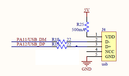
There is no "filtering" on your usb port. On my STM32F's I usually use 22 ohm resistors like they do on the dev boards. It cleans up the eye diagram of the USB.

enter image description here

As far as the rest of the design, it's probably not very noise proof. If you are having problems with random dropouts then the design is probably susceptible to external noise corrupting packs from USB and causing dropouts OR from common mode noise from the USB grounding.

If the design is experiencing dropouts when humans are near it or touching it, then it could be an ESD issue.

It looks like the diff pair lines from the USB are run a long way across the board, it's usually best to put the processor as close to the USB port as possible to minimize the diff pair length and transmission line effects that come from long diff pairs (easier than doing math). I also see other traces that are close to the USB diff pair, which could increase cross capacitance between traces, and lead to noise coupling (or even ESD coupling).

\$\endgroup\$
1
  • \$\begingroup\$ Thanks for the suggestions. Yes, I'm looking to re-design the board starting with the USB port and the oscillator and following it with everything else. I will include the 22 ohm resistors also in the design, that's a great tip. One question - do you think these are a big impact for USB FS also? That's only 12MHz IIRC. \$\endgroup\$ Commented Jan 7, 2020 at 3:04

Your Answer

By clicking “Post Your Answer”, you agree to our terms of service and acknowledge you have read our privacy policy.

Not the answer you're looking for? Browse other questions tagged or ask your own question.