0
\$\begingroup\$

I'm currently trying to figure out how to drive a bare 7-segment 4-digit LCD glass (without driver).

Part number of display: VI-415-DP-RC-S

I’m currently planning to apply a (min.) 30 Hz square wave to active segments. With VOn = 3V. The common pin of the LCD is currently planned to be at GND (0V)

Is that valid? Because I have read that DC is the worst thing that could happen to an LCD and I don’t know if a square wave is preventing the display from damage.

If I need a “real” AC source, is it valid to put 1.5V on the common lead of the display via a resistor ladder? This would result in a voltage from -1.5V to 1.5V on Segment pins.

If this is valid, which current should be flowing down the resistor ladder? And I assume that the segment off voltage then needs to be 1.5V —> 0V for the LCD between segment and common.

\$\endgroup\$

2 Answers 2

2
\$\begingroup\$

That's a static drive display, I believe.

You must keep the (average) DC voltage across the display (common to any segment) to less than some small amount like 50mV (read the specifications).

What you generally want to do is drive the common with a square wave at, say, 60Hz, and drive each segment with a square wave that is either in phase or out of phase with the common. You can do that with a microcontroller, with an FPGA or with discrete logic. Ideally a microcontroller with an LCD peripheral on board, but it's not necessary if you have enough I/O pins.

It might be possible to tie the common to Vcc/2 and either drive the segment with a square wave or make it high-Z, but the capacitive coupling could make the segment partly on in the second case, and (in)accuracy of the divider might result in some DC voltage across the segment. The latter is probably okay if you use 1% resistors and the same supply as the driver.

\$\endgroup\$
6
  • \$\begingroup\$ Okay thank you. I think I definitely have to order the lcd first and do some testing before I can order my prototype pcb. Also because the datasheet is awful. This is the best I could found: mouser.de/datasheet/2/422/VI-415-336751.pdf and it contains no specifications or information on how to drive the display \$\endgroup\$
    – Ohjurot
    Commented Jan 7, 2020 at 23:23
  • \$\begingroup\$ You can check out the recommended driver IC datasheets- Oki MSM58292 and Hitachi HD61603. \$\endgroup\$ Commented Jan 8, 2020 at 0:42
  • \$\begingroup\$ Yes on the HD61603 Datasheet there is indeed some information about the driving voltage levels. But not much information about the driving timing. But my main mistake was that I only searched for 7seg lcd driver. I now found the NXP PCF2112, the datasheet actually contains very detailed information on how the ic is driving the display at static and different multiplexing modes. They are applying Vcc square wave at a frequency in or out of Phase on com and seg. However I already ordered some test lcd. So I will make some tests and scope measurements and keep you updated. \$\endgroup\$
    – Ohjurot
    Commented Jan 8, 2020 at 6:46
  • \$\begingroup\$ The LCD you picked is static drive so you don't need to worry about multiplexing and contrast/temperature stability will be good. The downside is that you need one pin for each segment (plus the common). The timing skew is determined by the maximum effective DC voltage and the frequency is not critical, 30-60Hz up to a few hundred Hz is fine, but lower frequencies will have less power consumption. \$\endgroup\$ Commented Jan 8, 2020 at 7:09
  • \$\begingroup\$ Yes that’s actually the conclusion the datasheet gave me. I think that I will use the NXP chip for the final prototype. But it was kind of a challenge for me to do this without a special driver. I will do some test on two segments to prove my understanding of the concept. My current design included 4 LCD BCD to 7seg converters with Latch so that I would only need 4 + 4(2 with decoder) io. But that actually is much more expensive than the NXP chip. So i will go with the NXP chip. There are also some pics with integrated lcd drivers. But for a static lcd it would require a (too) expensive one... \$\endgroup\$
    – Ohjurot
    Commented Jan 8, 2020 at 7:34
0
\$\begingroup\$

Thanks Spehro Pefhany for your answer and the nice discussion! I just want to summerice the discussion and my additional research combined with some images and a C++ code file.

The lcd mentioned in the Question is an static drive display. It is not valid to apply a static dc field between the segment electrode and the common electrode! It will destroy the display. The best way to avoid that is to alternate the voltage on the common pin between ground and vcc. Every segment that is on, must have the oposite potential than the common pin (ex.: Common: Hight --> Segment: Low). Every segment that is off, must have the same potential then the common pin (ex.: Common: Hight --> Segment: Hight). Normally an lcd is driven with a frequency around 30-60Hz (higher is not a fault, it just consumes more power)

For evaluation purpose I connected the common of the display to PA.0 of an ATTiny. In addition i connected two segments, one to PA.1 the other to PA.2: LCD Test setup
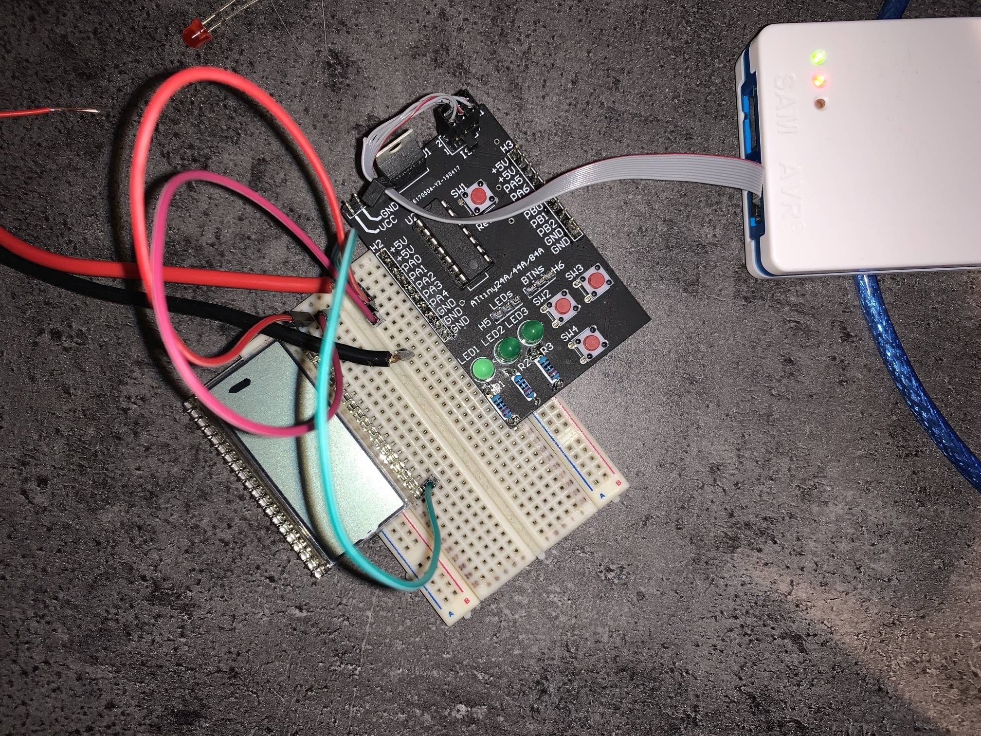
I used a timer and the compare interrupt to trigger the io change operation. The following cpp File was used to alternate between two segments:

/*
 * TryLCD.cpp
 *
 * Created: 11.01.2020 12:49:58
 * Author : Ludwig Füchsl
 * Description: Evaluation code for driving an static lcd glass directly with an ATTiny
 */ 
// 8MHz internal oscillator
#define F_CPU 8000000UL

// Include atmel libs
#include <avr/io.h>
#include <avr/interrupt.h>
#include <util/delay.h>

// Bit for common high low
bool bit = false;
// Segment a desired value
bool a = false;
// Segment b desired value
bool b = false;

// Output compare match interrupt 
ISR(TIM0_COMPA_vect){
    // Invert common every clock cycle to generate alternating field in lcd
    bit = !bit;

    // Set the current common state
    if(bit)     PORTA |=  (1UL << 0);
    else        PORTA &= ~(1UL << 0);

    // Determinate segment a state via xor with common
    if(bit ^ a) PORTA |=  (1UL << 1);
    else        PORTA &= ~(1UL << 1);

    // Determinate segment b state via xor with common
    if(bit ^ b) PORTA |=  (1UL << 2);
    else        PORTA &= ~(1UL << 2);
}

// Main program
int main(void){
    cli();

    // == Setup IO ==
    // Port A output
    DDRA    = 0xFF;
    // Port A all off
    PORTA   = 0x00;

    // == Setup Timer Meta ==
    // Clear on compare
    TCCR0A |=  (1UL << WGM01);
    // Timer prescaler clk/256
    TCCR0B |=  (1UL << CS02);

    // Setup Time Interrupt
    // Compare match A on 255
    OCR0A = 0xFF;
    // Compare match a A interrupt enable
    TIMSK0 |= (1UL << OCIE0A);

    // Interrupts on
    sei();

    // Setup default segment values
    a = true;
    b = false;

    // Main loop
    while (1) {
        // Wait for 1s
        _delay_ms(1000);
        // Invert a and b
        a = !a;
        b = !b;
    }
}

Using my test setup and this code, i took some measurement with my scope. On Chanel 1 (yellow) is the common. On Chanel 2 (green) is segment A (In this case the segment is NOT lit). On Chanel 3 (orange) is segment B (In this case the segment is lit) Scope measurement for lcd driving
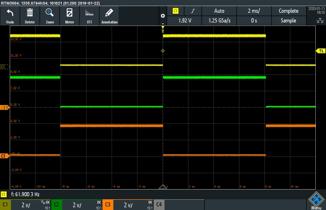
Please note that if you are not using an static lcd (Multiple commons) the lcd needs to be multiplexed! This results in the need of more that two voltage levels! For more information please also read this document by microchip: Application Notice 658

\$\endgroup\$

Your Answer

By clicking “Post Your Answer”, you agree to our terms of service and acknowledge you have read our privacy policy.

Not the answer you're looking for? Browse other questions tagged or ask your own question.