1
\$\begingroup\$

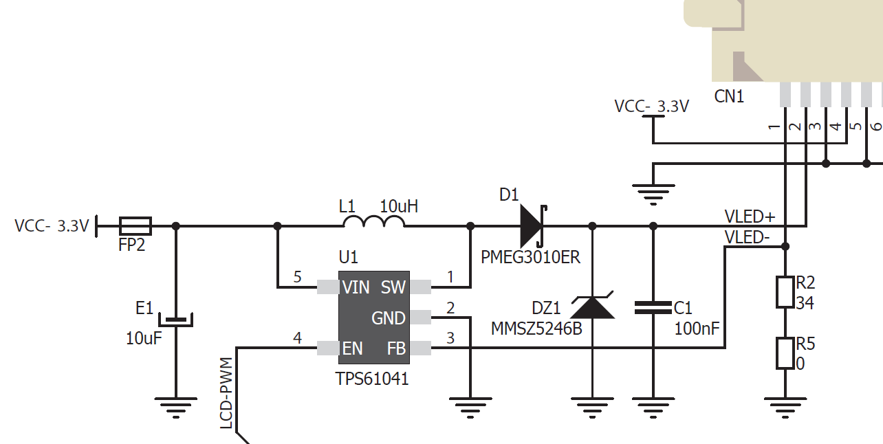
I have been working with a dev board with the LCD backlight circuit shown below. The boost converted used is the TPS61041. On page 18 of the datasheet, there is an example of the backlight circuit configuration.

I am trying to drive a NHD-4.3-480272EF-ASXN# 4.3" TFT. The TFT backlight requires 40-50 mA at ~25 volts. To make the circuit compatible, I have replaced R2 with a 27 ohm resistor for ~45 mA regulation. I have also removed DZ1 to prevent it from clipping the output at ~16 V. The TFT backlight still does not power on. I have checked all of the TFT connections and they are correct. I also have the EN pin set high. Where am I doing something wrong?

schematic

\$\endgroup\$
4
  • 1
    \$\begingroup\$ Have you measured the output at the SW to see what is being provided? Also what is driving the "LCD-PWM" signal, or do you have that tied to ground/high? \$\endgroup\$
    – Ron Beyer
    Commented Feb 11, 2020 at 15:01
  • 1
    \$\begingroup\$ I would try to locate the issue by disconnecting the LCD panel and replacing it with a resistor load. Like a 25 V / 45 mA = 560 ohms, 2 Watt resistor. If you don't have such a resistor, use a 100 ohm resistor (0.25 Watt will do) that should result in 100 ohm * 45mA = 4.5 V between VLED+/- That allows you to check that the boost converter is OK (or not). If not: what inductor are you using, did you follow PCB layout guidelines from the datasheet (if these are there). \$\endgroup\$ Commented Feb 11, 2020 at 15:18
  • 3
    \$\begingroup\$ BTW I tried putting your design into TI's Webench power designer and it said that it was an invalid design for that chip. Increasing VCC to 5V allowed it to continue, but it wouldn't generate a design for 3.3V input at 45mA/25 volt output. It's also odd that you aren't using a voltage divider on the FB side. \$\endgroup\$
    – Ron Beyer
    Commented Feb 11, 2020 at 15:18
  • \$\begingroup\$ @RonBeyer good work with the TI webench and maybe that constitutes an answer. The LEDs and both resistors form the feedback to keep current constant in the LEDs - it's a standard way of making a switcher drive constant current. \$\endgroup\$
    – Andy aka
    Commented Feb 11, 2020 at 15:49

1 Answer 1

1
\$\begingroup\$

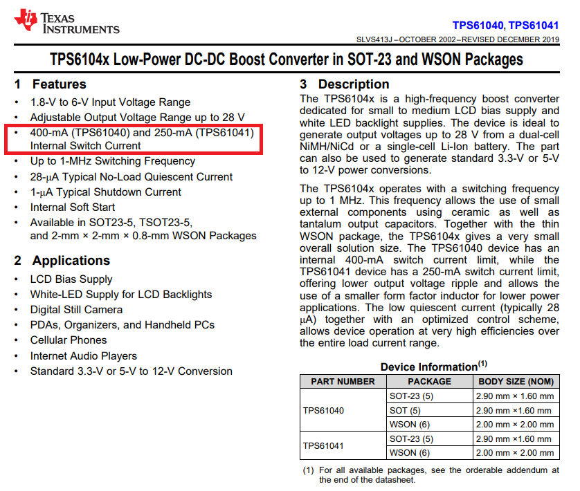
Look at the front page of the data sheet: -

enter image description here

The internal switch that causes the inductor to "charge up" is limited to 250 mA for the TPS61041. This means that going "balls-out", the maximum power that can be taken from the 3.3 volt supply is 0.825 watts. Inefficiencies might mean only 0.75 watts is delivered to the output load.

You want to drive 40 mA at 25 volts and that's a power requirement of 1 watt. Do you see the problem?

What is wrong with this LCD backlight boost converter circuit

Probably nothing - misapplication is the likely cause of the problem.

\$\endgroup\$
1
  • 1
    \$\begingroup\$ It's actually worse than that -- 250 mA is the peak current for the switch. Since the current through the switch is in general a linear ramp, the average current will be at most half that value, limiting the input power to only about 0.4 W. \$\endgroup\$
    – Dave Tweed
    Commented Feb 11, 2020 at 16:14

Your Answer

By clicking “Post Your Answer”, you agree to our terms of service and acknowledge you have read our privacy policy.

Not the answer you're looking for? Browse other questions tagged or ask your own question.