2
\$\begingroup\$

I am trying to automatically input a pin code into an electronic card reader so I can automate the process.

First thought was to build a small robot finger and control that to input the code, complexity vs benefits was too high for this option.

Second thought is to directly deliver power to the pressed buttons with a microcontroller.

Assumption: when a button is pressed, a switch is closed so current can flow through the circuit.

Question: how can I measure the current when a button is pressed? Where do I connect the multimeter on the electronics shown below.

Assumption: knowing the amount of current a pressed button delivers to the circuit, I can deliver the same amount directly via a microcontroller.

Question: where - given the layout of the board below - do I connect the microcontroller to each button on the circuit?

I am a computer science engineer with limited knowledge in electrical engineering, so directions and resources to help me solve this problem are greatly appreciated.

If you think there is a better way to being able to input numbers softwarematically into this card reader, do let me know!

The card reader looks as follows: enter image description here
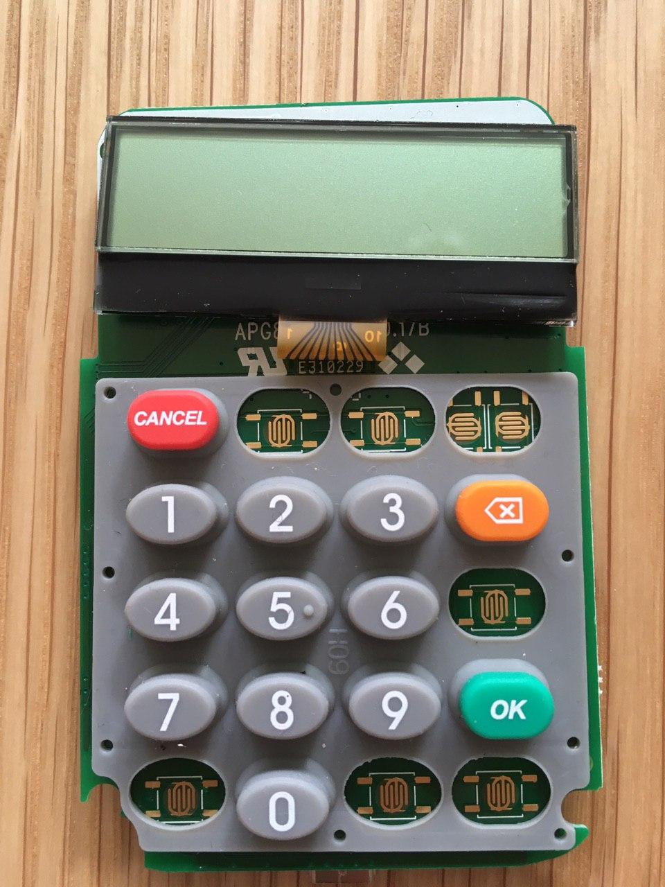
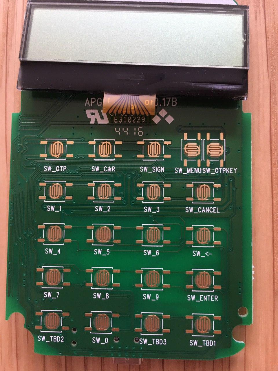
Electronics look like this: enter image description here

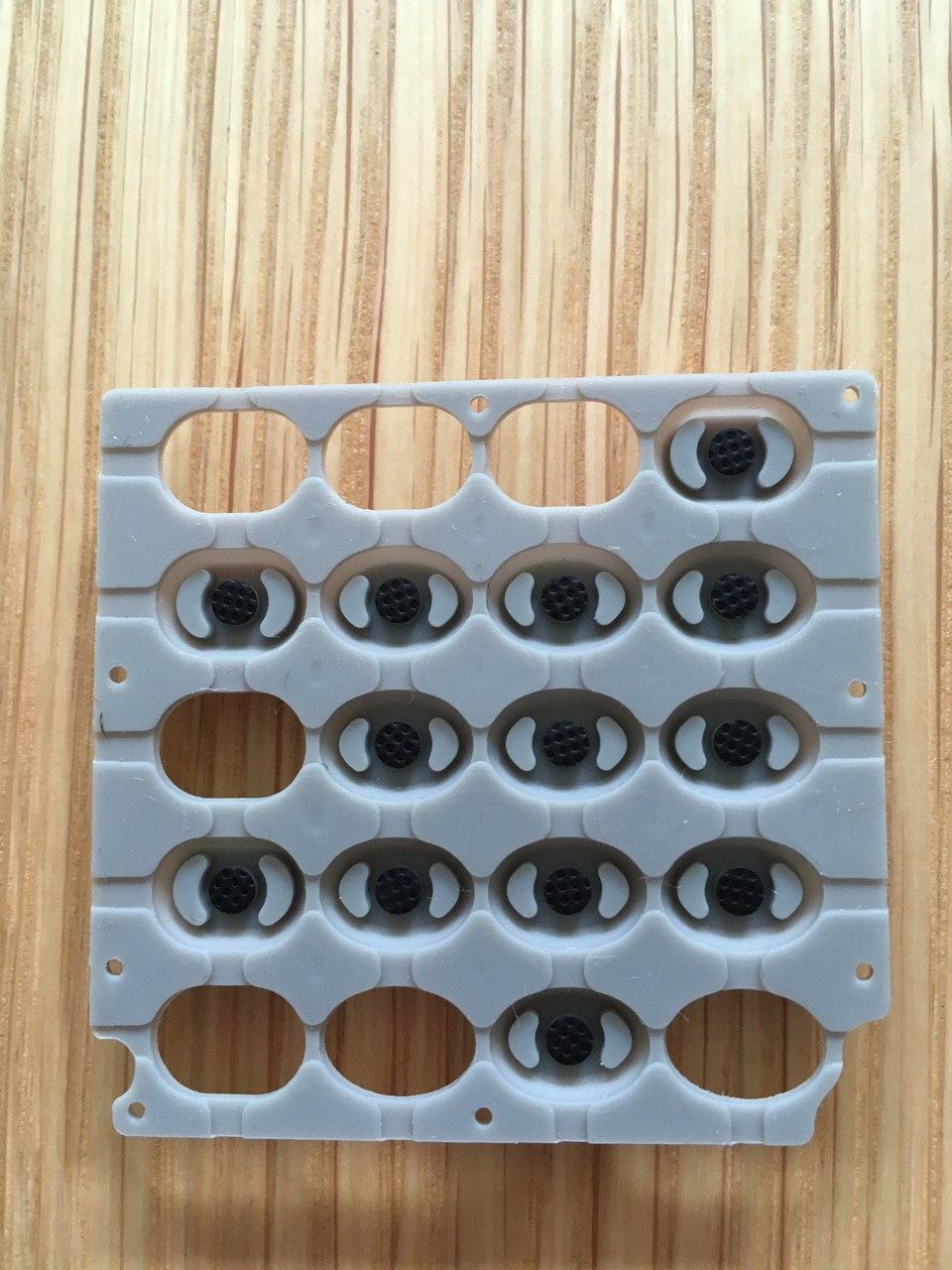
With the rear of the buttons looking like this: enter image description here

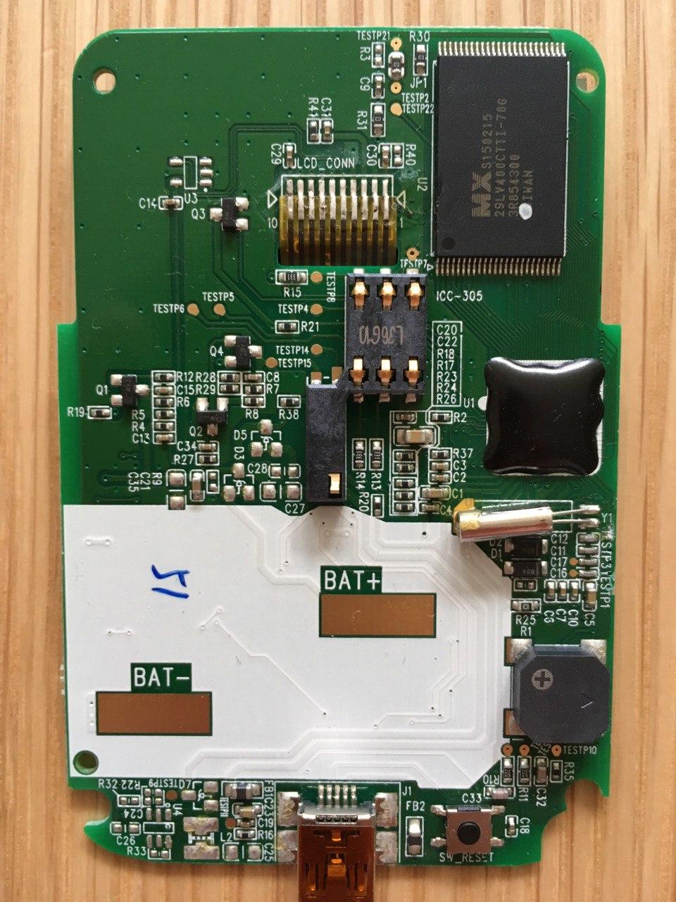
The rear: enter image description here

\$\endgroup\$
5
  • \$\begingroup\$ In engineering there are always tradeoffs to consider. A reasonable engineering answer for your question needs more information so that alternatives can be considered. With that said this question really needs an explanation of (a) Why you need to automate key pad inputs to this device. (b) What are the higher level goals you are trying to achieve. (c) Are you testing this device? \$\endgroup\$ Commented Feb 21, 2020 at 12:35
  • \$\begingroup\$ (a) I am automating a business process in software, however in one step a code needs to be input via this 3rd party card reader for authentication purposes. So I need to be able to input the code softwarematically. (b) higher level goal is being able to dynamically input a code via software without human interaction. (c) Yes. \$\endgroup\$
    – Lagastic
    Commented Feb 21, 2020 at 12:50
  • \$\begingroup\$ That input needs to go into your question. Your higher level goal is still not clear. If you are needing to automate the function of the keypad they why not just take it completely out of the equation and inject logical results into where the keypad fed its outputs. \$\endgroup\$ Commented Feb 21, 2020 at 12:57
  • \$\begingroup\$ Attaching wires to the PCB with solder connections is OK presumably. \$\endgroup\$
    – Andy aka
    Commented Feb 21, 2020 at 13:14
  • \$\begingroup\$ You're going about this the long way. Replace the keypad with whatever you need. \$\endgroup\$ Commented Feb 21, 2020 at 13:58

3 Answers 3

1
\$\begingroup\$

I'll somehow extend Cristobol's answer.

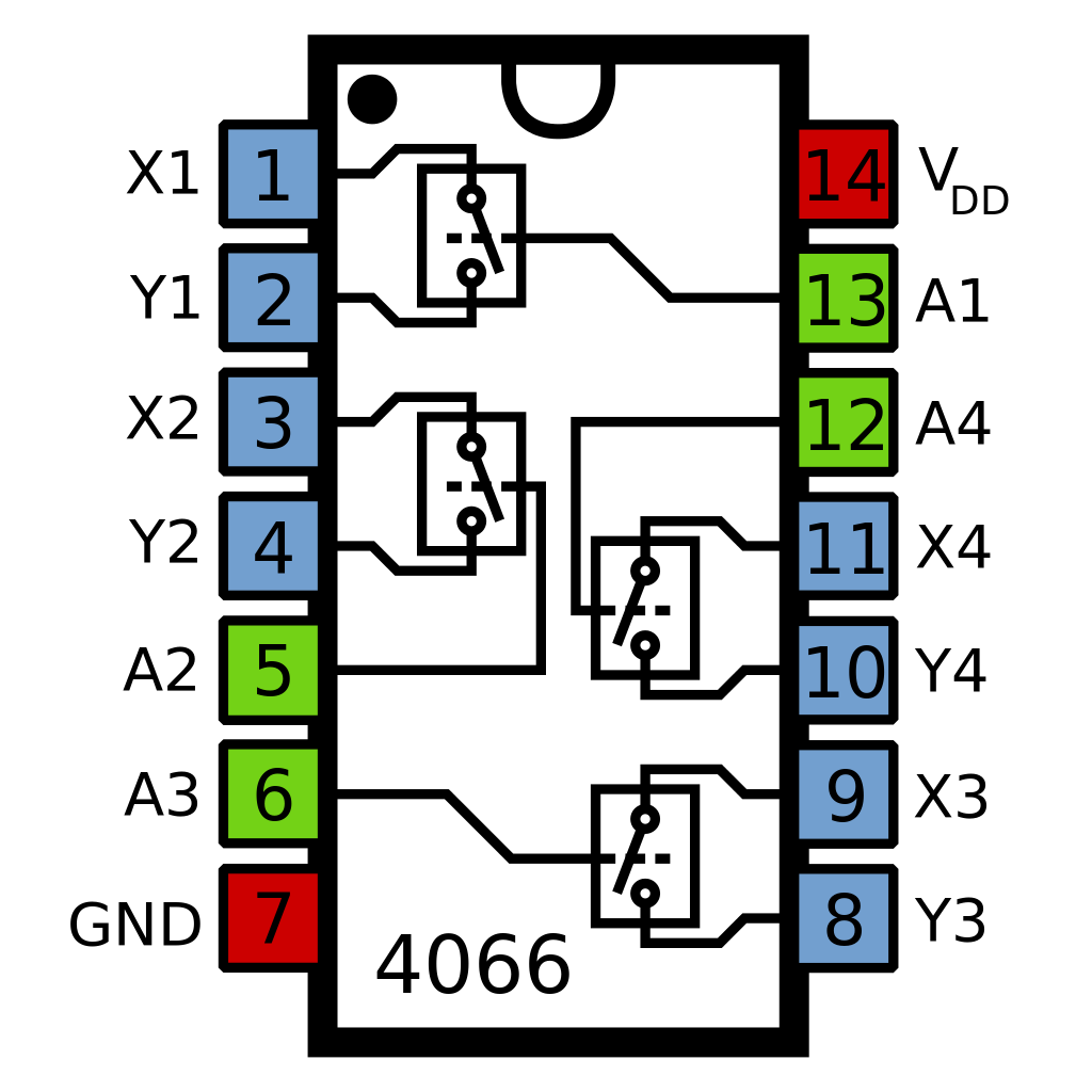
#1. More hardware, less software If you can spend 21 I/Os (assuming you want to simulate key presses on all the keys) you can use the CD4066 IC. It is an analog bilateral switch and each package includes four of these.

enter image description here

You can connect every key's two contacts to one of those bilateral switches and activate the switch using a single I/O. This is a generic solution and you don't need to worry about the keypad being multiplexed or not. It will also cost you a few ICs, microcontroller I/Os and ~100 solder points. The software is as simple as it can be: you simply time some pulses on the correct pins simulating the key presses.

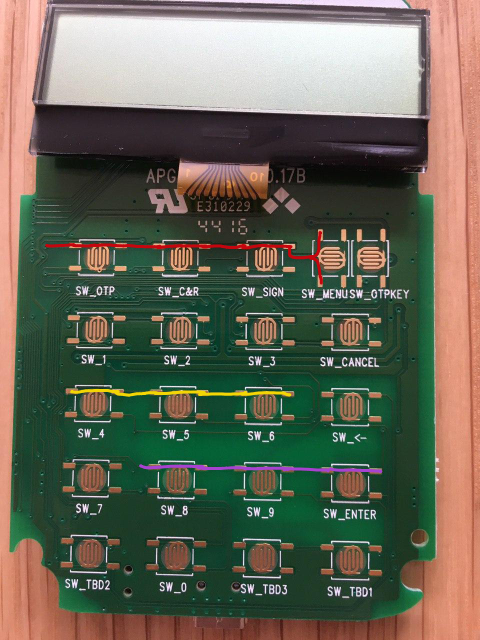
#2. More software, less hardware You most probably have some sort of multiplexed array. The traces I've highlighted below suggest common row connections between keys.

enter image description here

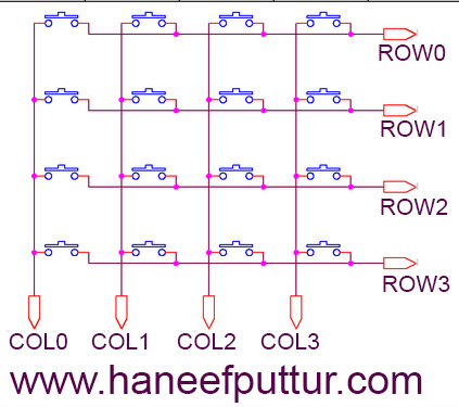
Multiplexed matrices look like the image below.

enter image description here

Just like Cristobol said, scanning it involves actively driving one side (either columns or rows) and reading the other side (rows or columns, respectivelly). You might want to attach an oscilloscope to it and figure out which traces are being driven. After that, with a multimeter, try to understand how these keys are connected between each other. If the traces are being driven slowly enough (say, 1kHz) you can wait for them to be selected (reading with the microcontroller) and then writing on the specific lines being read by the keypad controller. You'll also need to figure out the polarity of this "select" signal, and if the lines being read have pull-up or pull-down resistors. This will require minimal external hardware (only the microcontroller and some wires, assuming the keypad controller and your uC operate at the same voltage) and about 20 solder joint (9+1 for colums/rows + GND on the keypad, then double that on the microcontroller).

\$\endgroup\$
1
  • \$\begingroup\$ Thank you, your answer along with Cassimaster and Cristobol's answer provided me with the necessary information to proceed. :) \$\endgroup\$
    – Lagastic
    Commented Feb 24, 2020 at 19:48
2
\$\begingroup\$

Those inputs are probably matrixed, since I don't see any obvious ground traces. Matrixing means that you drive one side of some switches low, and read the other side to see which one is pressed, then drive some others low and read them with the same input lines. Matrixing allows this particular keypad to be read with 9 I/Os instead of 20, but it means driving high and low in an uncoordinated manner can result in errors.

You could figure out the matrixing sequence--which side of each button is driven vs. which side is read, and use AND or OR gates to handle the multiplexing--but it would probably be much easier to use analog switches driven by your controller. Those would simulate the operation of the mechanical switches.

The analog switches can be connected across the top and bottom (redundant) terminals, or if your soldering skills are very precise, connecting across the fingers is also an option.

\$\endgroup\$
1
\$\begingroup\$

Yes, you could possibly measure the Voltage and apply it to the corresponding Button, but: It's easier than you think: The black circles on the inner side of the Buttons are made out of conductive material, wich close the circuit on the PCB. You can exploit this by using some sort of "external Button" to activate a Button.

You can see four conducting rectangles for each button, where both on the top and both on the buttom are connected together. My best guess is to solder two thin Wires (one to the upper and one of the lower) to all Buttons each. If you hold them together, the corresponding button should be activated.

To achieve this with a microcontroller you can use some sort of a Relay (wich would work), but you should use something like a "Optocoupler", because you would hear the clicking of the Relais and Optocouplers are cheaper. You'll need to connect both wires of a button to one Optocoupler and the other side to a microcontroller like an Arduino and GND.

(Just an Example for an Optoucoupler) https://www.ebay.com/itm/30PCS-PC123-DIP-4-Optoisolator-Photocoupler-Optocoupler-Triac-Driver-IC/401774709561

You can use a multiplexer if yout microcontroller has not enough Pins.

\$\endgroup\$

Your Answer

By clicking “Post Your Answer”, you agree to our terms of service and acknowledge you have read our privacy policy.

Not the answer you're looking for? Browse other questions tagged or ask your own question.