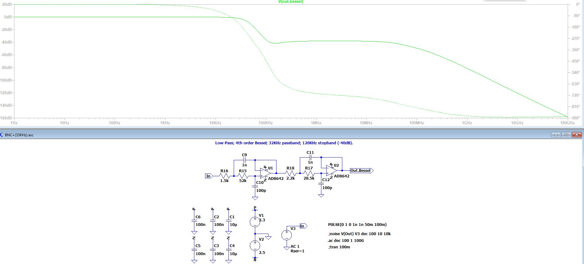
Welcome all. I designed Bessel low pas filter using Analogue Devices filter wizard. It is a fantastic toll saving loads of time. However, like any tool has its limitations. Upon completion my design I checked datasheet for suggested filter. Sadly, one of parameters voltage offset drift is bit higher than I can accept (2.5uV/*C). Therefore, I am looking for precision op-amp however not sure how to approach swapping AD8642 for precision op amp. What spec should I prioritize? Currently critical spec I am looking at is Gain bandwidth product, supply voltage and offset temperature drift. Also, can anyone explain flatness of a response between 100KHz and 80MHz? Usually in this type of filter I observed roll-off and peaking and high frequency rather than flat response.
3 Answers
Also, can anyone explain flatness of a response between 100KHz and 80MHz?
Yes, the AD8642 runs out of steam and can no longer convincingly perform the sallen key task asked of it. It has a bandwidth of only 3 MHz before its open loop gain drops to unity. Don’t expect great things of this device above about one tenth of that frequency.
So, once the opamp runs out of steam, the output impedance rises and you might as well pull the chip from the circuit. You still get an output because the input signals cut through the resistors and capacitors fairly freely.
-
\$\begingroup\$ Thank you for your reply it makes sense now. \$\endgroup\$ Commented Mar 2, 2020 at 17:35
The flatish response from 100kHz upwards is due to the rising output impedance of the opamps due to their low GBW product. Capacitors C9 and C11 rely on the amplifier having a zero output impedance. However, into a finite impedance, they allow a high frequency signal to feed forward from the resistor junction directly to the output, bypassing the filter.
There are three mitigations for this effect. The first is to use an amplifier with high GBW, and so high loop gain at the problem frequencies. The second is to raise the general impedance level of the filter components, so that the amplifier output impedance is a smaller fraction. The third is to use an odd-order Sallen-Key as the first stage, which comes with a real RC to ground, so taxes the amplifier output impedance less.
The shape of the plot shows you that even the AD8642 is short on GBW for the filter you want, if the stopband is important. Finding a fast, precision opamp may be expensive. It may be cheaper and easier to use a hybrid approach, so replacing each of U1 and U2 with a pair of buffers in parallel. Use a fast buffer with a low output impedance and no need for DC accuracy to drive the feedback capacitors. Use a relatively slow precision amplifier to buffer the voltage to the next stage.
-
\$\begingroup\$ Thank you very much for your answer I will look into it! \$\endgroup\$ Commented Mar 2, 2020 at 17:34
kudos to Walt Jung of Analog Devices Inc (and of other companies) for explaining this, many decades ago.
If you want -100dB response from an active filter at some frequency (that is, 100dB attenuation in the Stop Band), then that opamp must provide cancellation of signals to within 0.001% ( or better) at that frequency.
In other words, the "free" attenuation at high frequencies we expect from a passive R+C low pass filter (assuming smart grounding), is most expensive to achieve in an active filter, because the opamp(s) must be extremely precise even at the high frequencies.

