1
\$\begingroup\$

I am trying to design a third order Butterworth filter with Sallen–Key topology. I am quite new to this and there is not much only about third order variations.I have the following requirements:

  • Gain: 1 (unity)
  • Passband (cut off): 116 Hz
  • Stopband: 500 Hz
  • Stop band attenuation: ≥ 35 dB

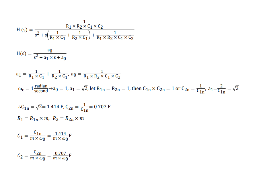
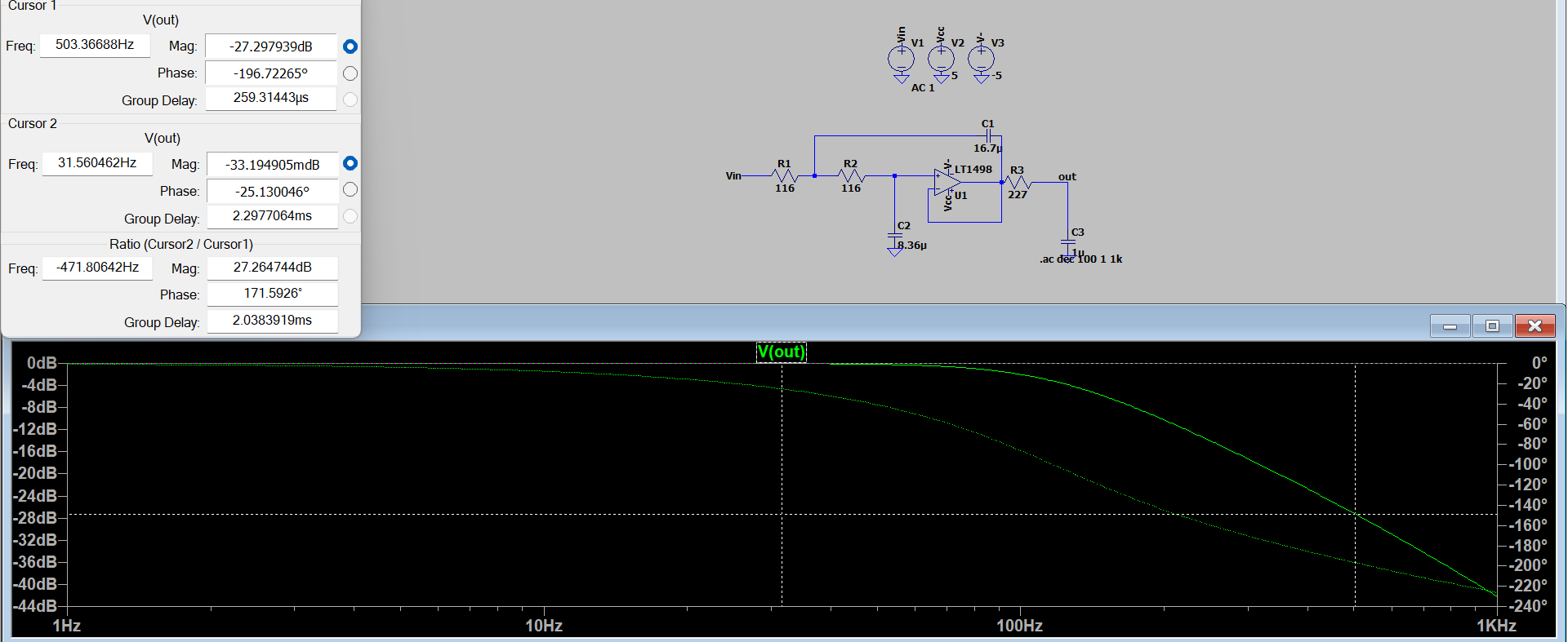
I thought I could make the original sallen key configuration into a third order by simply adding an RC circuit at the output, then calculating both of the fc to be 116 Hz. The 2nd order circuit was calculated by normalizing the resistor and capacitor values by setting fc to 1 rad/s, then scaling up (method shown in image). These values where multiplied by m = 116 (resistor) and 1/116 (capacitor), yielding:

  • R1 & R2: 116 ohm
  • C1:16.7 μF
  • C2:8.36 μF

With this the passband is correct (116 Hz at -3 dB), however obviously the attenuation is not steep enough to yield the passband attenuation. I am not sure on how to configure the third order section and was wondering if I could get some assistance on this. This is a revision piece, where we were told to make a third order butterworth filter with sallen key topology.

filter schematicsallen key 2nd order calculation

\$\endgroup\$
17
  • 4
    \$\begingroup\$ I think your issue here is that you're misunderstanding the filter order of Butterworth filters. Proper Butterworth filters are supposed to form poles equidistant along the unit circle. The 2nd order filter you calculated has this property. But if you simply tack on a first order RC (always located at s=-1 + 0j), then the resultant filter as a whole does not have its poles equidistant anymore. The 2nd order section must be calculated such that when you add the RC section, the entire filter as a whole has all three poles properly spaced. \$\endgroup\$
    – Ste Kulov
    Commented Dec 19, 2023 at 23:52
  • 2
    \$\begingroup\$ @confusionpersonified For example, a 2nd order Butterworth has \$\zeta=\frac12\sqrt{2}\$. But a 3rd order Butterworth has its 2nd order section with \$\zeta=\frac12\$. Do you know that fact? Or why? \$\endgroup\$ Commented Dec 19, 2023 at 23:54
  • 1
    \$\begingroup\$ @confusionpersonified Check out Figure 5-26 of this free online book. It's a table of Butterworth pole locations and properties. You can find the Q for each imaginary pole pair, and then use something like this calculator (scroll down to 2nd part) to enter in that Q value. Basically you split a design into independent 2nd order sections (and an additional 1st order if it's odd numbered). \$\endgroup\$
    – Ste Kulov
    Commented Dec 20, 2023 at 0:03
  • 1
    \$\begingroup\$ @confusionpersonified A simple RC would have the same shape as an opamp buffered one. And it is the right shape for the 1st order stage (which because its Q is lower should go first in the chain) of the Butterworth. So you have a good answer below without the need for a 2nd opamp. If that qualifies for you, I'd go with it. \$\endgroup\$ Commented Dec 20, 2023 at 1:37
  • 1
    \$\begingroup\$ @confus The relative ratios of C1, C2, and C3 (shown in the answer below) are determined by solving for three equations based upon the real root, and the real part and the imaginary part of one of the complex roots. That's three equations and three unknowns: C1=3.54681827688408, C2=1.39264678170264, C3=0.202451072765786. \$\endgroup\$ Commented Dec 20, 2023 at 9:00

1 Answer 1

3
\$\begingroup\$

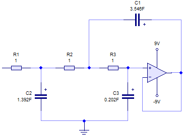
From the standard tables, the circuit configuration you require with the resistor and capacitor values normalised to 1 rad/sec is as below....

Filter design

First we must frequency scale the capacitors.

C1 = 3.546 F/(2 * pi * 116) = 4.87 mF

C2 = 1.392 F/(2 * pi * 116) = 1.91 mF

C3 = 0.202 F/(2 * pi * 116) = 0.277 mF

Next we must impedence scale all the component values to get realistic values.

Choose a standard value for C1 and calculate the impedence scaling factor

let C1 = 100 nF

Impedence scaling factor = 4.87 mF/100 nF = 48.7k

C2 = 1.91 mF/48.7k = 39.2 nF

C3 = 0.277 mF/48.7k = 5.69 nF

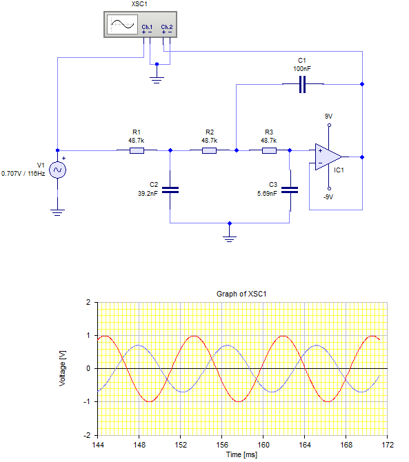
R1 = R2 = R3 = 1R * 48.7k = 48.7k

Final circuit...

Final Filter

As you can see the output is 0.707 down (-3 dB) at 116 Hz.

Although the component values are not standard values, their values are in the right ball park to be practical.

\$\endgroup\$

Your Answer

By clicking “Post Your Answer”, you agree to our terms of service and acknowledge you have read our privacy policy.

Not the answer you're looking for? Browse other questions tagged or ask your own question.