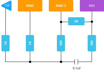
This AOSP/Develop/Audio page describes the following audio loopback dongle. Can someone explain it?
To ensure that the output signal will not overload the microphone input, we cut it down by about 20dB. The resistor loads tell the microphone polarity switch that the audio loopback dongle is a US/CTIA pinout Tip Ring Ring Shield (TRRS) plug.
Tip is left channel output, ring is right channel output, ring 2 is ground, and mic is the microphone voltage. In other words, the left and right channels are combined and fed into the microphone circuit.
- I assume the microphone polarity switch refers to the 1K, 1K, 100, 100 resistors. What is a microphone polarity switch and how does it relate to the resistors?
- I assume the 2K resistor is to prevent shorting the microphone input? To get the referenced -20dBv this implies the phone's internal microphone circuit resistance is about 20K (seems a bit high...)?
- What is the point of the 0.1uF capacitor? A coupling capacitor... between what?
And lastly, if I were to build this myself, any gotchas to avoid?
edit
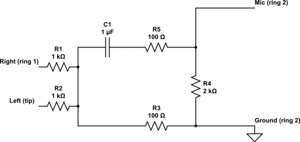
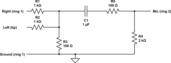
The circuit clicked when I redrew it (below). But I still have some questions:
- What is the point of R3 and R5?
- R4 is - I assume - the virtual microphone load. Is this the resistor that interacts with the "microphone polarity switch"? A TRS plug would create a short between Mic and Ground but otherwise doesn't have anything to do with polarity.
R1 and R2 prevent overloading the microphone input. Does the -20dBv refer to these resistors in parallel?
1K||1K = 2K
20 * log(2K/x) = -20
x = 20K
That would imply headphone impedance averages 20K, but research shows most headphones average well below 1K. How can I explain the quoted -20dBv?
edit: That's a mistake,
x = 5K. Still high though.An answer below suggests R1 and R2 are also necessary for mixing the left/right signals. Are resistors required when mixing out-of-phase signals?
And C1 keeps the mic bias voltage out of the line outputs. (yeah I originally thought the microphone generated its own voltage; that there was no bias).

simulate this circuit – Schematic created using CircuitLab
Can someone redraw the diagram with signal and voltage sources? I'd probably botch it up. As well as an oscilloscope across R4? I'm curious if the capacitor would distort human speech at 50Hz - 1000Hz out-of-phase inputs on the right and left channels. I found this rule of thumb:
- 100Hz - 10uF
- 1000Hz - 1uF
So 0.1uF (in the source diagram) looks a little low.


