What does the Holding Current characteristic mean on a triac?
What does this mean for switching loads less than the Holding Current?
For example the Sharp S108T02 has a max 50 mA Holding Current.
What does the Holding Current characteristic mean on a triac?
What does this mean for switching loads less than the Holding Current?
For example the Sharp S108T02 has a max 50 mA Holding Current.
To answer this, consider the simpler to understand SCR instead of a triac. A triac is sortof two SCRs back to back and therefore can pass current in both directions. A SCR only works one way but has the same issue of holding current.
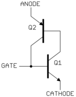
Here is a equivalent circuit of a SCR:

SCRs are actually built as one integrated device, but you can conceptualize them as two transistors like this. In fact, you can even make a scr from a NPN and PNP transistor like this if you just want to experiment.
Look at this circuit carefully and see how it works. If somehow a little current were to flow thru one of the transistors, let's say Q1, that causes base current to flow thru Q2, which causes even larger base current thru Q1, which then turns on Q2 even more, etc. Once a little current starts flowing, this circuit latches on.
Now imagine current is flowing and the gate is left open. As long as the current continues, the circuit acts like a switch in the on state. However, below some level of current, the cascading amplifying effect can't be sustained anymore, and the circuit switches off. This minimum level of current so that the device is guaranteed to stay on is the minimum holding current.
This circuit only works with current flowing in one direction whereas triacs work in both directions, but the concept of the minimum current to keep the device on is the same.
Once you switch a relay on (whether it is solid state or mechanical) there is some amount of current required to hold it in the "active" state. Essentially, this is telling you that the device which switches the relay on and off must be able to deliver up to 50mA at the switching voltage in order to keep the relay connected (or disconnected, depending on whether or not this is a normally open or normally closed relay).
This doesn't imply anything about the amount of load across the relay, only the amount of load required to connect the terminals.
EDIT:
So looking at the datasheet I realized that the question you were asking was not about solid state relays but triacs. The characteristics for a triac are pretty unique.
Essentially, the idea is that a triac will conduct AC current once triggered until the output current drops below the threshold called the holding current. So in answer to your original question: your load must exceed 50mA for as long as you would like it to conduct.
I would recommend tracking down some reference designs using triacs, they are NOT the same thing as a solid-state relay.
As Mr. Lathrop notes, once a triac has been switched on, it will remain on without any further gate-signal or optical stimulus, provided a certain amount of current flows through the device. If the specification had listed both a minimum and maximum holding current, that would mean that the device would be guaranteed to remain on if the current was greater than the specified maximum holding current, and guaranteed to switch off if the current fell below the specified minimum. At current levels between the specified minimum and maximum, the triac could arbitrarily decide to remain on or switch off and comply with the specification.
Since this particular triac does not specify a minimum holding current, it should probably be regarded as being bounded by the "off" leakage current (if the level of current the device leaked when "off" exceeded the holding current, that level of current would cause the device to spontaneously switch on, rendering it rather useless). If the device happens to only leak 0.5nA when off, the device could remain on with 0.6nA flowing through it and comply with the specification. The device is designed to be used in AC-switching applications, such that the applied voltage will switch polarity periodically. Consequently, even if the holding current happened to be a fraction of a femptoampere, the change in polarity would ensure that the device switches off. On the other hand, if the voltage between the switched pins did not switch polarity but merely went down to a fraction of a microvolt, the specification would not guarantee that such a voltage would not keep the device switched on.
(In practice, a microvolt of forward bias would certainly be way too low to allow any current to keep flowing, but one should not rely upon that. There exist other devices where the minimum holding current is specified to be significantly above zero; if one needs the thing to switch off without a polarity reversal, one should use one of those other devices).