1
\$\begingroup\$

I seem to have bought the wrong solenoid valve. It takes 24v (I assume AC), and I just tested the supply and it is 46vac. The valve obviously works at that voltage, but it sometimes makes a loud groaning noise, and I worry about damaging it. At this point, I can't return the valve, so I want to figure out how hard it would be to reduce the voltage of the input.

The valve listing is here, but I'll list the electrical specs below:

Input Voltage: 24V

Current Draw: 160mA

Power Consumption: 3.84 Watts

Can I just put a resistor on there? If so, what specs should the resistor have?

\$\endgroup\$
2
  • 1
    \$\begingroup\$ It is a tough call to say that the solenoid valve is for 24VAC. Without a proper data sheet from the manufacturer it appropriate labeling right on the valve it could just as well be 24VDC. \$\endgroup\$ Commented Apr 17, 2020 at 16:07
  • \$\begingroup\$ The impedance of an AC valve is likely to change as the armature moves. If it's a DC valve, you might build a small rectifier/regulator to power it. \$\endgroup\$
    – Neil_UK
    Commented Apr 17, 2020 at 16:10

3 Answers 3

2
\$\begingroup\$

Input Voltage: 24V Current Draw: 160mA Power Consumption: 3.84 Watts

I think there's significant doubt as to whether the device is an AC operated valve. This is made worse by the link not being clear but, in general, if the supply voltage is stated as 24 volts AND the current specified is 160 mA then it's highly likely that the power dissipated will be exactly 3.84 watts on a DC system.

This is because voltage x current = power and 24 volts x 160 mA = 3.84 watts.

If it were an AC solenoid then it's highly unlikely that the power dissipated will be exactly 3.84 watts.

So, running a 24 volt DC solenoid from 46 V AC is not going to survive too long. Try researching the part better and find out what the requirements really are. I think you'll find it to be a DC solenoid. You need to confirm this first before any further answer can be made to help you sort it out.

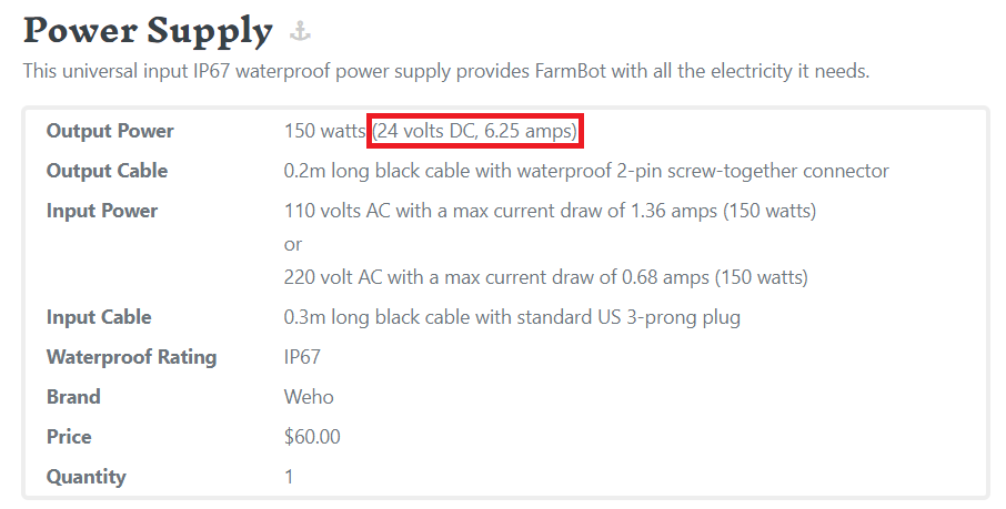
If you check out the sort of power supplies supplied by FarmBot (your linked supplier) they are 24 volt DC: -

enter image description here

\$\endgroup\$
2
  • \$\begingroup\$ Would 46VAC open a 24VDC solenoid (because it does)? Would the alternating current explain the vibration in a solenoid designed for DC? \$\endgroup\$ Commented Apr 17, 2020 at 16:27
  • 1
    \$\begingroup\$ If it does it does but it will over heat more than likely and fail. The AC would certainly explain the vibration. \$\endgroup\$
    – Andy aka
    Commented Apr 17, 2020 at 17:08
2
\$\begingroup\$

Input Voltage: 24V

Current Draw: 160mA

Use a multimeter to measure the valve's DC resistance. If you measure 150 ohms then it is specified for DC: 24V/150R = 160mA. If you measure a much lower resistance value then it's probably specified for AC.

However the FarmBot's power supply is 24V DC so the solenoid is most likely specified for 24V DC.

So... problem is to convert 46V AC into something that can drive your valve. I assume it's 46V RMS, not peak, right?

Simplest solution would be to measure the AC current in the solenoid with 46V AC power and add a 5W resistor in series to drop current to 160mA RMS. Resistor value will depend on solenoid inductance, so you can either measure the inductance and do the math, or wing it and try various values.

If it still vibrates and groans, then maybe it is designed only for DC. In this case you'll need a rectifier and a way to drop the voltage down. You could use a 1:2.5 transformer to drop 46VAC down to 18.5VAC which should end up close to 24V after rectification and smoothing. If solenoid inductance is high enough you may not need a smoothing cap.

A 1:2.5 transformer is basically an off the shelf 110V to 48V transformer (more or less) with output current of at least 160mA, so 10-20 VA.

You could also just rectify and smooth the 46VAC power which will give about 64VDC but then you'll need a step down converter which is probably going to be hard to find given the unusual voltage.

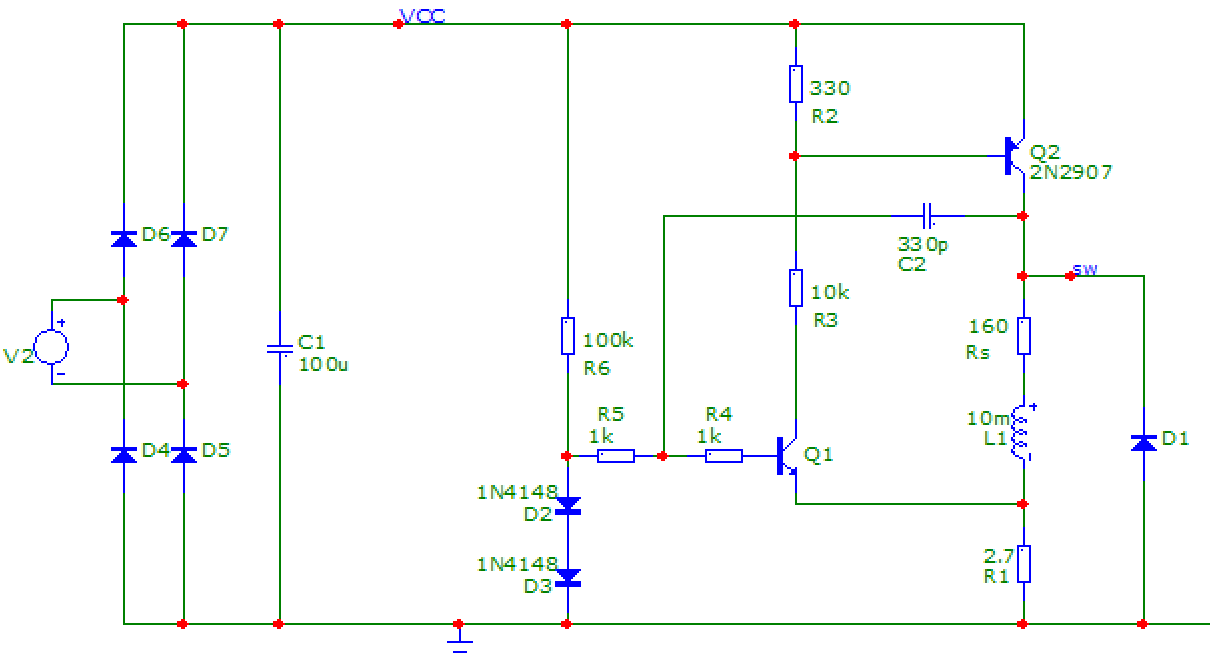
So here's a simple 2-transistor hysteretic switching constant current driver. The inductance L1 is the solenoid, Rs is its internal resistance.
enter image description here

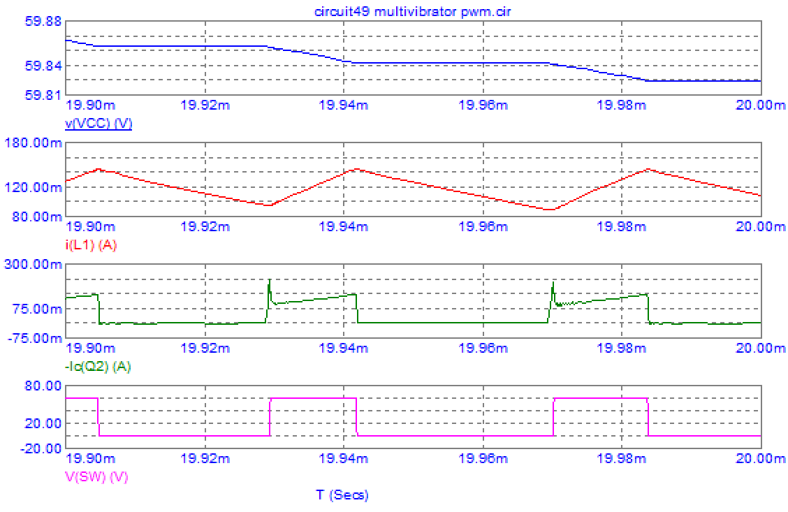
When it is powered up, D2/D3 create a 1.2V reference and Q1 turns on, trying to keep its emitter at 0.6V above ground. Q1's collector current turns Q2 on, and current begins to rise in the inductor. When current through L1 is high enough so voltage on R1 reaches 0.6V, then Q1 turns off, turning Q2 off, and current decreases. Then the cycle repeats. C2 is the important part as it provides feedback and hysteresis which allow the circuit to oscillate. C2 also sets the oscillator frequency. Without C2 it would be a simple linear constant current driver.

Simulated switching waveforms:
enter image description here

Note this circuit has an "ENABLE" input to turn it on or off, it's the top of R6 which is connected to the power supply, but you can use a signal from a microcontroller or anything else to control it.

\$\endgroup\$
2
  • \$\begingroup\$ Playing with this in another simulator suggests that 100 kΩ may be too high for R6. The diodes don't turn on enough to make it work. It works if I replace the diodes with 1N4007s, though. \$\endgroup\$
    – Hearth
    Commented Apr 17, 2020 at 19:14
  • \$\begingroup\$ Maybe add a decoupling cap in parallel with the diodes... This schematic is a bit quick & dirty, I went for junk bin parts only, no shopping allowed due to global deadly virus pandemic... \$\endgroup\$
    – bobflux
    Commented Apr 17, 2020 at 23:10
0
\$\begingroup\$

schematic

simulate this circuit – Schematic created using CircuitLab

Rather than a resistor, which will waste power and generate heat, you can use a single series diode to produce a half-wave unsmoothed rectifier. This will produce an average DC voltage of 0.45 x the RMS supply voltage (reference) so your 46 V AC supply will become 20.7 V DC.

In case that's a bit low for your 24 V valve to operate reliably (but try it first) you can boost the voltage by adding a small smoothing capacitor in parallel with the valve. I suggest starting with a 4.7 or 10 μF and increasing it until you get reliable operation (or you can do the calculus to get the right value first time).

A 46 V AC supply will have a peak value of 65 V so the diode and, if needed, capacitor should have a working voltage comfortably in excess of that for reliability, e.g. 100 V. An electrolytic capacitor will need to be connected with the correct polarity to suit the diode. As @Hearth suggests below, do not use more capacitance than needed or you could supply excessive voltage to the valve.

\$\endgroup\$
2
  • 3
    \$\begingroup\$ Note: do not use a capacitor large enough to properly smooth the voltage! If you do that, you'll just be applying 65 V DC to it, effectively. \$\endgroup\$
    – Hearth
    Commented Apr 17, 2020 at 20:00
  • \$\begingroup\$ Indeed. The valve may work on less than the stated 24 V so try without a capacitor first and if it doesn't work add the minimum capacitance required to make it work reliably. \$\endgroup\$
    – Graham Nye
    Commented Apr 17, 2020 at 20:14

Your Answer

By clicking “Post Your Answer”, you agree to our terms of service and acknowledge you have read our privacy policy.

Not the answer you're looking for? Browse other questions tagged or ask your own question.