1
\$\begingroup\$

I want to use a switching boost converter that has 3.3V output in order to power an SD card. Also, the input voltage is a CR2477 battery, with voltage ranging from 2 to 3 volts. I have seen that an SD card may require up to a maximum of 100mA during writes. As a result, I found this boost converter: TLV61225DCKR .

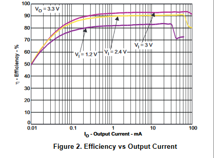
As you can see in the link above, the output current is said to be 400mA on the site. However, by checking the datasheet of the converter, I found out that 400mA is the switch current limit. Furthermore, from the datasheet, I saw this figure:

enter image description here

This figure was the only reference I could find for output current, and the problem is that the efficiency falls dramatically at around 100mA, where the axis ends. I do not understand why on the farnell site the output current is rated as 400mA. Is this an error of the farnell site? Also, could you explain what exactly is the switch current limit "Isw", as mentioned in the datasheet?

Lastly do you have any recommendations for such a boost converter? The important aspect is to be as efficient as possible during those 100mA peak current writes.

\$\endgroup\$
1
  • \$\begingroup\$ "This figure was the only reference I could find for output current..." - What about Figure 1? \$\endgroup\$
    – marcelm
    Commented Apr 28, 2020 at 20:46

2 Answers 2

1
\$\begingroup\$

That battery can't provide such currents, not for the SD card, and not for the booster. Maximum current draw is typically 15mA. It is meant for typical 0.2mA loads.

\$\endgroup\$
4
  • 1
    \$\begingroup\$ To add to this, the battery probably has around 100 ohms of internal impedance, so even if you try to draw a high current (which will damage the battery), the absolute max power you can get out is ~25mW, which will be at 1.5V \$\endgroup\$
    – BeB00
    Commented Apr 28, 2020 at 20:25
  • \$\begingroup\$ Great point. Do you have any design alternatives I could consider, perhaps adding a large capacitor to handle the high current requirements? The project is a small scale embedded system that needs to store data from an accelerometer, for 4 months, at 10Hz. The trick part is that the whole weight should not exceed 30grams, and the size should be 50mm X 40mm X 20mm \$\endgroup\$
    – NickG
    Commented Apr 28, 2020 at 21:25
  • \$\begingroup\$ 4 months is roughly 3000 hours. For example a 1000 mAh lithium ion battery weighs 22 grams. You need to get average consumption below 0.33 mA. What is the consumption of the accelerometer and the MCU now? \$\endgroup\$
    – Justme
    Commented Apr 28, 2020 at 21:56
  • \$\begingroup\$ @Justme I apologize, I meant to say I need to store on-system data for 3 weeks, that would be around 280Mbytes. The battery life however should be at around 4 months. The accelerometer needs around 10uA. I will be using an ATmega328p, so when active, it needs 5.2mA and powered down it needs only 4.2uA. Should I consider an alternative form of storage as well? \$\endgroup\$
    – NickG
    Commented Apr 28, 2020 at 22:55
0
\$\begingroup\$

The SCL is essentially the peak current you can have in your switching waveform. If you want 100mA out, you'll need a pretty large inductor with 160mA minimum SCL. That's why the efficiency drops off at higher currents.

You may need to consider your choice of battery as well. Coin cells aren't particularly good at switching larger currents, and have a very low life when delivering high currents with a large duty cycle. For this type of battery, 20-50mA is a high current, and you'll need to deliver over 200mA for writing in your application.

\$\endgroup\$

Your Answer

By clicking “Post Your Answer”, you agree to our terms of service and acknowledge you have read our privacy policy.

Not the answer you're looking for? Browse other questions tagged or ask your own question.