2
\$\begingroup\$

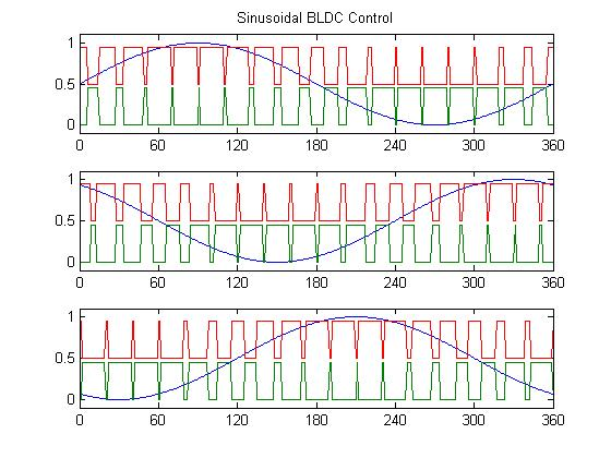
In the diagrams that I have seen showing the PWM plots vs the sign wave of the high and low side fets for each phase of BLDC sine commutation, they are shown as being the inverse of each other:

Sinusoidal BLDC Control

Please could someone explain why it is preferable to drive the gates on inverse signals? (ignoring deadtime for the purposes of this question)

IE Why is it better to pull a phase to high during the off cycle of the low side, rather than leave it floating when you actually want current flowing out of the low side of that phase? e.g. at 240 degrees on phase A

Obviously while the sine is positive for a phase, the high side would be needed, and in order keep the bootstrap capacity charged it will also need switching to low side during the off part for the high side - so that side of it I can see an explanation for - though I may be missing the whole picture and I am unsure why the entire inverse is the best setting, when only a fraction of that should be needed to keep the boot capacitor charged.

However when the sine value is negative for the phase, I do not see the reason for the high side gate being active at all (eg for phase A from 180 degrees to 360 degrees)?

Is this related to an inductive property of the windings that I am missing?

Note I am specifically looking for what the benefits might be in terms of optimal operation of a BLDC motor, such as avoiding torque ripple or other losses of those are factors.

\$\endgroup\$
9
  • \$\begingroup\$ Are you basically asking why some MOSFETs are not held at a constant on or off during each half cycle. If you are then the answer is simply - they can be and to do so will save switching losses. If you mean something else then maybe try re-phrasing your question. \$\endgroup\$
    – Andy aka
    Commented May 3, 2020 at 9:13
  • \$\begingroup\$ Andy, if they can be, why does every single plot I can find on sine commutation show the high as always being the inverse of the low? That sounds like the is a reason behind it - since as you say, all else being equal not switching would save losses. \$\endgroup\$
    – Simm
    Commented May 3, 2020 at 9:23
  • 2
    \$\begingroup\$ I asked a qustion on this a few years ago because i came to the same conclusion as you - electronics.stackexchange.com/questions/130069/…. I thought I'd stumbled upon something but, it turns out that this is done quite often. \$\endgroup\$
    – Andy aka
    Commented May 3, 2020 at 9:34
  • \$\begingroup\$ But that doesn’t really refer to the effects on BLDC commutation, how it might affect torque ripple or the other BLDC motor specific aspects here \$\endgroup\$
    – Simm
    Commented May 3, 2020 at 9:38
  • \$\begingroup\$ Well, you never asked about torque ripple or other BLDC motor specific aspects so, if you haven't asked for these in your question, how can anyone help? This EE site isn't particularly noted for any degree of clairvoyance qualities. \$\endgroup\$
    – Andy aka
    Commented May 3, 2020 at 9:43

3 Answers 3

3
+50
\$\begingroup\$

Top part of the question, why are the motor windings being switched both positive and negative if the phase should be mostly positive, this is because with inductive loads like motors, the current is out of phase with the voltage. as such for each phase, when the average voltage may be positive, the phase angle of the motor coil can mean that it should be shunting a ratio of current to the lower rail for that point of the waveform,

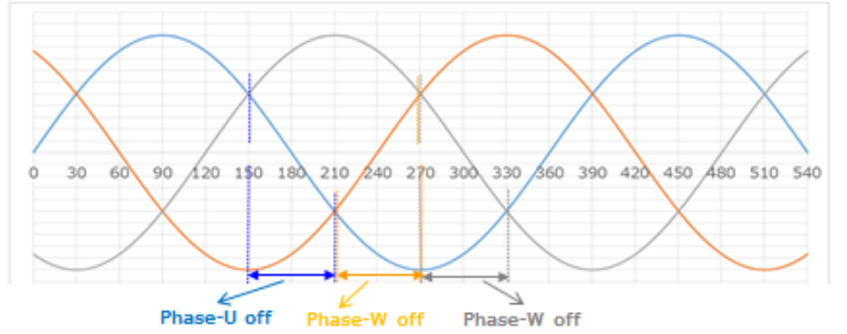
Each phase influences the others, so by keeping the phase low or high at that point allows current to be fed through a different phase at the correct point and in the correct direction. (Green is voltage, Yellow is Current)

Green is Voltage, Yellow is Current

The exact name of the pattern used is called "180 degree commutation". while what your imagining is "120 degree commutation", the downside with 120 degree commutation is that it only makes use of 2 of the coils at any one time, meaning you loose some efficiency (input power vs rotational power) and it is a bit noisier as you have spikes of acceleration during the change over periods,

by extending the high and low mosfets to each be active for half of the waveform you can make that third phase do some work and smooth out those transitions.

enter image description here image source

As to the second part, why there are small pulses during the lowest and highest points, is that on average over any PWM time, it will be a non-zero value, so it remains switched on for some very small percentage of the waveforme,

Extending from this, in the real world pulses like that is also useful for measuring the phase currents to determine the position of the rotor to keep the control system lined up

Most BLDC controllers will measure the low side currents of 2 or all 3 phases to determine the exact direction of the rotor, and from that if it is leading or lagging, by correcting for this the controller can make sure the maximum amount of torque is available from the motor over its entire rotation,

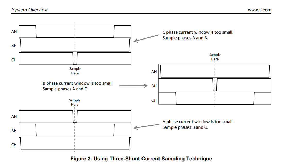
Depending on how many phases your measuring the current in, additional pulses at the crests and peaks may need to be added, as if 1 phase it switched low, and the others high, you only have 1 low side measurement, from that you cannot tell what ratio of that current the other 2 phases are, which means you do not know the position of the rotor anymore.

As to why switching one of the phases high / low at these points is not an issue. you might notice on both my and your diagram that all phases are to the same switched side when these pulses happen,

enter image description here TI application note on the subject

\$\endgroup\$
5
  • \$\begingroup\$ But why is it better to pull a phase to high during the off cycle of the low side, rather than leave it floating when you actually want current flowing out of the low side of that phase? eg at 240 degrees on phase A \$\endgroup\$
    – Simm
    Commented May 6, 2020 at 10:48
  • \$\begingroup\$ I have reworked my answer a little for you, the PWM period is not infinitely thin, so the on time percentage will be what it needed to be over that entire period, based on where it was in the phase curve, leaving it on for the full cycle would mean a small amount more current would flow through the other phases than it should, causing a change in acceleration, and making the motor more noisy. \$\endgroup\$
    – Reroute
    Commented May 6, 2020 at 11:29
  • \$\begingroup\$ I completely understand that you wouldn't leave it on for the full cycle, my question is why, when the current is existing on the low side of a phase, is the high gate on that phase turned on to the inverse of the low gate on that same phase? That is what is shown in every diagram I can find showing the PWM pattern - I want to understand why. I already understand why you would use sine commutation and why at any given time you would be using either 2 high and 1 low or 2 low and 1 high gates - one from either phase, with varying duty cycles on the pulse width. \$\endgroup\$
    – Simm
    Commented May 6, 2020 at 12:00
  • 1
    \$\begingroup\$ You have that inductor sinking current to the lower rail while the other 2 are held high. If you open the low side switch of that phase what happens? It tries to keep sinking current by increasing its voltage. As such if you left the high side mosfet open it would bypass through its body diode to the upper rail anyway. This both heats up the mosfet more than if it was just switched to the rail for this period. And would slow the motor more by having a higher voltage drop with the same current (acting lile a generator for that breif moment) \$\endgroup\$
    – Reroute
    Commented May 7, 2020 at 1:12
  • 1
    \$\begingroup\$ Shorting the wires of the motor do not have a significant braking force. You have the back emf voltage and the coil current. The maximum braking force is whem you have a resistance loading it around the maximum for those values. By having only the motor windings resistance which is very low. And the mosfet resistance which is low. You have the full current but almost no voltage. So the total power of the braking force is small. When you add the fixed drop of about 1V from the body diode. That makes it much more significant. \$\endgroup\$
    – Reroute
    Commented May 7, 2020 at 1:29
3
\$\begingroup\$

Look at one of its (other 2 seem similar). You don't need to think too complicate let's think this way. it's 4 N-chanel FET.

  1. If read signal go high, high side of phase will conduct, and phase voltage be +V.
  2. If green signal go high, Low side of phase will conduct, and phase voltage be -V.
  3. The motor act like Low-pass filter so it average signal voltage so we can calculate from duty cycle of V+ and V- To make this assumption true, we must keep phase voltage V+ Or V- so we can average its. If you make float state (high impedance) the formula can't be true because we can't define voltage of floating pin (actually it will depend on Back EMF) to make it precise sine wave it has to done this way.
\$\endgroup\$
2
  • \$\begingroup\$ The phase voltage will never be -V though - you can have a negative phase to phase voltage, but the lowest voltage will only be ground. \$\endgroup\$
    – Simm
    Commented May 6, 2020 at 9:03
  • 1
    \$\begingroup\$ Yes but it we can simply V+ = vin, V- = ground it’s equivalent. \$\endgroup\$
    – M lab
    Commented May 6, 2020 at 13:01
2
\$\begingroup\$

The trick here is to minimize interference as much as possible.

Lets start with a simplified view.

In sine-wave BLDC control, you want to supply the motor with 3 sine-waves 120 degrees offset from each other. If you would try to do this with just an analog voltage, it would prove very inefficient. Thus modern motor controllers apply a PWM signal and let the motor filter it. By insuring that at least one side of each half bridge is on, we can model the system as follows.

enter image description here

By then varying the PWM of each "switch", the motor will smooth it out and behave as if it is getting 3-phase AC. This technique is called SVM (Space Vector Modulation).

This article explains it in more detail https://www.switchcraft.org/learning/2017/3/15/space-vector-pwm-intro

\$\endgroup\$

Your Answer

By clicking “Post Your Answer”, you agree to our terms of service and acknowledge you have read our privacy policy.

Not the answer you're looking for? Browse other questions tagged or ask your own question.