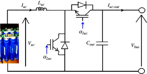
Simple uni-directional Buck-Boost without resonant caps using "Supercaps".

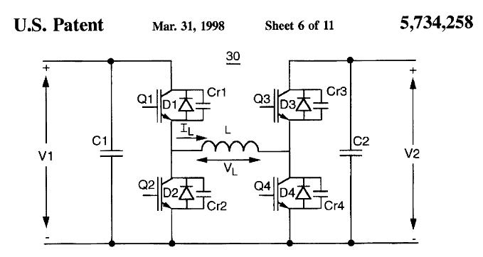
Bi-directional Buck-Boost using resonant caps on each switch.
(More efficient but more complex dead-time commutation control)
Imagine a regenerative braking car in this arrangement with the battery voltage on the one side and motor/generator on the other side, and the demand to accelerate and brake the motor in an intelligent phase control controller (Not shown for simplicity). (There may be many parallel MOSFETS to reduce the Ron value)
...or a dual source power supply which can be charger on left and battery on right.
These are some of the patented and licensed waveforms used to regulate the resonant switching commutation of the Buck-Boost high efficiency regulators.


You can read the patent for theory of operation. This is just intended to wet your appetite of the complexity of a bi-directional Buck Boost controller switch. Voltage and current sensing is an important aspect to optimize commutation duration when the switch voltage drop is minimal. Resonant switch Capacitors & Diodes during free-wheeling play an important part in the commutation to make it loss free.
These charts show the On state of each transistor with the thick bar, not the voltage or current. Each phase is carefuly controlled according to state of V1-V2 and power demand.
Optimal range is typically 1:1 to < 2:1 for voltage ratio of the bigger side.


