0
\$\begingroup\$

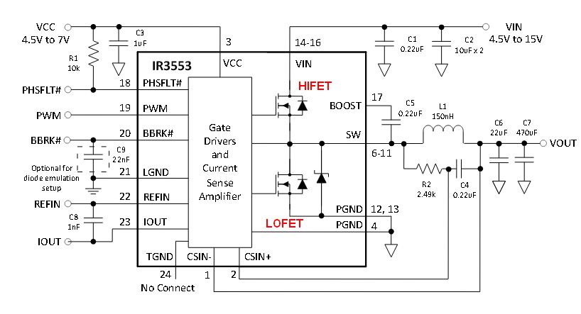
I was going through available synchronous buck converter ICs with external PWM capability (which can be controlled with the help of a micro-controller) and i found this one for e.g. I have read in a post here that synchronous buck converters are bidirectional in nature. So keeping that in mind this chip IR3553 should also be bidirectional (i.e it should be able to deliver current from and to both sides if required). Is it so ? For e.g if i charge a battery using this chip and after charging i simply replace my power supply with a Load, will this IC be able to supply the current to the load from the battery ?

Ive gone through its data sheets, and many other IC's datasheets, but i couldn't find any information related to its bidirectional use. So if anyone has experience with such ICs or knows about such ICs, can you please answer my question ?

Thanks in advance!. Comments would be highly appreciated

Thankyou!

\$\endgroup\$
3
  • \$\begingroup\$ which way is the direction of regulation then? Surely there must be an "input" and an "output" for something like a buck regulator, whether or not it fails to have a reverse-blocking mechanism built-in \$\endgroup\$
    – KyranF
    Commented Jun 2, 2015 at 15:55
  • \$\begingroup\$ well during the first phase (battery charging phase) it should work like a Buck converter i.e stepping down the Voltage from the power supply and supplying it to the battery. Once the battery is charged, the power supply is replaced by some load, and now (in second phase) the battery supplies power to the load. However, in the second phase its not important weather the IC acts like a buck or a boost controller, i just want it to deliver power from the battery to the load. \$\endgroup\$
    – yiipmann
    Commented Jun 3, 2015 at 12:33
  • \$\begingroup\$ Well I don't think the devices can do this for you, but some simple power-path management with some diodes or MOSFETs can set up this behaviour for you \$\endgroup\$
    – KyranF
    Commented Jun 3, 2015 at 15:17

2 Answers 2

4
\$\begingroup\$

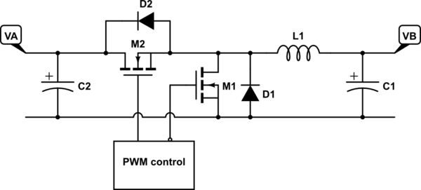
If we use somewhat simpler diagrams than Andy's, we can see the similarity a little more clearly. I'm showing the switching elements as MOSFETs, and I'm showing the associated body diodes explicitly, because this will become important later. For now, we'll ignore the details associated with driving the MOSFET gates, other than to say that when one is on, the other is off, and the duty cycle is variable. Starting with the buck converter:
schematic

simulate this circuit – Schematic created using CircuitLab

The normal flow of current is that when M2 is switched on, current flows through it and L1, charging the inductor with magnetic energy. When M2 switches off and M1 switches on, the current continues to flow through L1, discharging its stored energy.

Now, if M1 wasn't there, the circuit would still work, because the discharge current would still flow through D1. However, once L1's current drops to zero, the diode would block any further flow — this is known as "discontinuous conduction mode". Whereas with M1 present, the current flow can actually reverse. In other words, with active (synchronous) rectification, the converter can both source and sink current at its output. This is known as "continuous conduction mode". This means that the relationship between the input voltage VA and the output voltage VB is only a function of the duty cycle of the switching:

$$VB = VA \frac{T_{M2}}{T_{period}}$$

Note that if the current in L1 does go negative, when M1 switches off and M2 switches on, this briefly forces current back toward VA and C2, until the voltage across L1 causes the current to ramp back up to zero and then positive again.

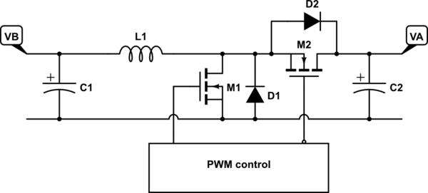
Now, let's look at the boost converter, which is an exact mirror image of the buck converter:
schematic

simulate this circuit

In normal operation, M1 switches on first, charging L1 with magnetic energy. Then, M1 switches off and M2 switches on, allowing the stored energy to discharge into C2.

Again, we could eliminate M2 and allow D2 to do the output switching, but M2 allows current to flow either way during the discharge phase. And just like with the buck converter, this means that the input-output voltage relationship becomes a function of only the switching duty cycle:

$$VA = VB \frac{T_{period}}{T_{M2}}$$

Note that this is a simple rearrangement of the terms in the equation for the buck converter — in other words, it's the same equation. This tells us that regardless of which way the power is flowing, the relationship between VA and VB is simply a function of the switching duty cycle.

So, to turn this into a concrete example, if the PWM control is set up so that M2 is on \$\frac{5}{12}\$ = 42% of the time, you could apply 12V at VA and get 5V out at VB, OR you could apply 5V at VB and get 12V out at VA!

REGULATION

One final note: This circuit provides a specific ratiometric relationship between the two voltages that is based on the duty cycle of the switching. If the input voltage is unregulated, but you want a regulated output voltage, then you need to provide a mechanism that varies the duty cycle of the switch in order to cancel out the input variations. Note that this control could be based on measuring the input voltage (feedforward) or measuring the output voltage (feedback).

If you're going to build a practical bidirectional power converter with regulation, you'll have to pay extra attention to how this control mechanism works in both modes.

\$\endgroup\$
8
  • \$\begingroup\$ Thanks alot for your detailed description. I got all what you said. As far as regulation is concerned i dont think that would be an issue because input voltage wont be varying. However my original question was, will an IC like this one be able to do the job ? that is to operate in a way that you described ? because its a synchronous buck converter, and according to the theory you explained, it SHOULD work like that, right ? any comments ? \$\endgroup\$
    – yiipmann
    Commented Jun 5, 2015 at 14:20
  • \$\begingroup\$ Yes. That's just a driver chip, and you control the PWM duty cycle directly. As long as you operate it at a fixed duty cycle, it will work as described above. \$\endgroup\$
    – Dave Tweed
    Commented Jun 5, 2015 at 21:55
  • \$\begingroup\$ Thanks! can you please also tell me about one more thing. I will charge battery through this buck converter from the AC mains. And once the charging is complete, i will discharge the battery with the help of a load. During this whole procedure i dont want to rewire my circuit, so i will have to replace my Power supply connection (which was used to charge the battery) and replace it with the load's connection (for discharging). So my question is that which type of device is used to do that? I searched online and found that Relays are used to do such thing. \$\endgroup\$
    – yiipmann
    Commented Jun 15, 2015 at 14:21
  • \$\begingroup\$ But i am confused with what kind of relay should be used ? as there are 1,2,3,4,6 pole relays available. Would a single pole relay work in my case ? and what specifications should i look for in its data sheet ? for e.g voltage/current, or any other thing ? I will be using a 12V,50A power supply to charge my battery. and my battery rating would be 3.7V 40A. so can you please tell me would a single pole relay do the job ? also what else to look for in its data sheet ? \$\endgroup\$
    – yiipmann
    Commented Jun 15, 2015 at 14:24
  • \$\begingroup\$ Also there are two type or relays, electro mechanical relays and solid state relays. I have read their differences. But dont know which one would be more suitable to use. One link said that electro mech relays are used when current is upto 15A. and solid state relays have higher currents upto 100A. So which one should i go for ? solid state ? as my current is around 50A ? \$\endgroup\$
    – yiipmann
    Commented Jun 15, 2015 at 15:00
2
\$\begingroup\$

A synchronous buck regulator can usually be turned into a synchronous boost regulator. Here's a a picture of the IR3553 and I've labelled the two FETs HI and LO: -

enter image description here

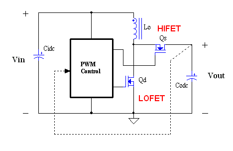
The above is how it is conventionally used (as a buck converter). Now, consider its similarity with a synchronous boost converter: -

enter image description here

Again, I've labelled the FETs HI and LO to match the original circuit.

Ignoring how the PWM control part receives power, it should be fairly clear (back to front of course just to confuse things) That Vin immediately above corresponds with Vout on the top diagram AND Vout immediately above corresponds with Vin in the top diagram.

So, forgetting about how the controller receives power, the two FETs and the inductor are interchangeably wired. However, this does not mean it will necessarily work, because the controller may sulk and frown from some subtlety held deep within its data sheet.

The bottom line is that synchronous buck converters ARE NOT bidirectional but you may be able to implement a boost conversion when wired in reverse.

I'm no expert on the IR3553 but I suspect it might get in a tangle with the bootstrap capacitor (that ultimately feeds high voltage power to the "HIFET"). It does have a seperate (non-integrated) Vcc pin so maybe it might work (but probably not as a bidirectional buck converter).

\$\endgroup\$
3
  • \$\begingroup\$ "so maybe it might work (but probably not as a bidirectional buck converter)"...can you please tell what do you exactly mean by this statement ? i mean it wont work as a bidirectional buck converter , or it wont work in a bidirectional way at all ? because initially it working as a buck converter is important, however when current hence power direction is reversed, its not important for it to work as a buck converter, its just important for it to supply power to the load from the battery. i.e it may be acting as a buck or a boost at that instant.. I hope i made my point clear. \$\endgroup\$
    – yiipmann
    Commented Jun 3, 2015 at 12:38
  • \$\begingroup\$ Theoretically a synchronous buck, in reverse becomes a boost converter. \$\endgroup\$
    – Andy aka
    Commented Jun 3, 2015 at 12:41
  • \$\begingroup\$ yes, thats what i had in my mind too. and that is what i was trying to say that i dont have any problem with it working as a boost converter, i just want it to work i.e to deliver power. And i hope it does, because i am just a beginner in using power electronics circuits practically. \$\endgroup\$
    – yiipmann
    Commented Jun 3, 2015 at 12:43

Your Answer

By clicking “Post Your Answer”, you agree to our terms of service and acknowledge you have read our privacy policy.

Not the answer you're looking for? Browse other questions tagged or ask your own question.