1
\$\begingroup\$

I would like to use a micro controller to read the position of a switch.

The example and image below is for illustration purposes only.

For example if a switch is at Position A, a 5V signal might feed DIGITAL INPUT 1. Similarly if the switch is at Position B, a 5V signal might feed DIGITAL INPUT 2. To make the signals useful, they would be on exclusivity to the other.

i.e.

Position A   Position B   |   DIGITAL 1      DIGITAL 2
--------------------------|----------------------------
    ON          OFF       |     HIGH          LOW
                          |
    OFF         ON        |     LOW           HIGH

The circuit is powered by the micro controller's 5V supply, and shares a common ground with the micro controller.

Thank you.

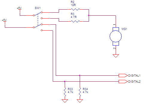
EDIT: changed R1 (1 kOhm) to a DC motor, to better represent the actual circuit.

Also, the input voltage has an error or +-0.5V. The resistors have a 5% error tolerance.

enter image description here https://www.circuitlab.com/circuit/wec9n2/switch-sensing/

\$\endgroup\$

4 Answers 4

2
\$\begingroup\$

While I was drawing the schematic with a DPDT switch, Pete had beat me to the answer.

enter image description here

\$\endgroup\$
2
  • \$\begingroup\$ Say I wanted to add a third switch position with another resistor. Do switches with 3 throws like this exist? \$\endgroup\$
    – waspinator
    Commented Nov 27, 2012 at 16:49
  • 1
    \$\begingroup\$ found some \$\endgroup\$
    – waspinator
    Commented Nov 29, 2012 at 2:39
4
\$\begingroup\$

If you can, replace the switch with a DPDT switch, and use the second pole to feed a digital input pin. In this case the second pole could be used to switch +5V or groud to the digital device input.

If you can not, you could use an instrumentation amp to sense the current through one or both resistors, setting the gain so that the output is a logic high level when the motor is drawing current through the resistor and is a logic low if not. (Being careful not to overdrive the digital input level.)

\$\endgroup\$
5
  • 1
    \$\begingroup\$ Why use an instrumentation amplifier? Why not a comparator? \$\endgroup\$
    – The Photon
    Commented Nov 27, 2012 at 2:05
  • \$\begingroup\$ @ThePhoton It depends on where current sensing is done. If the current sense resistor is on the low side of the motor, then comparator(s) provide a nice solution. A high side current sensing would still require a current mirror or an InAmp. \$\endgroup\$ Commented Nov 27, 2012 at 2:29
  • \$\begingroup\$ LM311 has input common mode range to Vs-1.2. My go-to in-amp (AD8221) has input common mode range to Vs-1.1. Either one needs some kind of shift to work in this application. But a simple voltage divider would probably be accurate enough for this simple case, and work with either part. But the comparator costs roughly 1/10 what the in-amp does. \$\endgroup\$
    – The Photon
    Commented Nov 27, 2012 at 2:41
  • \$\begingroup\$ OK, scratch what I said about using a simple voltage divider --- The signal you're looking for is less than 1% of the ~5 V common mode voltage. \$\endgroup\$
    – The Photon
    Commented Nov 27, 2012 at 3:02
  • \$\begingroup\$ Using an instrumentation amp designed for high side current sensing, like the AD8202, would be appropriate. Using a current sense amp allows one to use an existing resistor for current sensing, rather than adding a low side sense resistor to use with a comparator. Multiple approaches could work here. \$\endgroup\$
    – B Pete
    Commented Nov 27, 2012 at 4:20
1
\$\begingroup\$

Remove R1 (replace it with 0 ohms), and connect the nodes labeled "position 1", "position 2" directly to "digital input 1" and "digital input 2". It will behave exactly as you described.


Edit (after resistor values added):

When the switch is at B, node B will read 5V and A will read the voltage divider from the other branch: 1000 / 1018 * 5V = 4.91V. When the switch is at A, node 'A' will read 5V and B will read 1000 / 1004.7 * 5V = 4.98V. So, a comparator set at 4.95V on node A will let you distinguish the two cases with just a single digital input.

\$\endgroup\$
4
  • \$\begingroup\$ R1 cannot be removed as it's part of the circuit. The 3 loads must be where they are. Otherwise, yes, it would be a trivial problem. \$\endgroup\$
    – waspinator
    Commented Nov 27, 2012 at 0:11
  • 1
    \$\begingroup\$ Set its value to 0. If you can't, you'll have to tell us what its value is. Our crystal ball is not as clear as you might suspect. \$\endgroup\$
    – Jim Paris
    Commented Nov 27, 2012 at 0:12
  • \$\begingroup\$ ok, I added some values. I didn't realize they played a role in a solution. Thanks. \$\endgroup\$
    – waspinator
    Commented Nov 27, 2012 at 0:17
  • \$\begingroup\$ could you recommend a comparator to use? Would the LM193A work? To set a comparator at 4.95V you would need a voltage source at 4.95V right? would I use a voltage divider to create that? How robust would this solution be? It seems the tolerances are very low. (0.04V and 0.03V). Thanks. \$\endgroup\$
    – waspinator
    Commented Nov 27, 2012 at 1:08
0
\$\begingroup\$

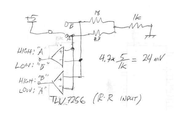
Your requirements are kind of nonsensical, but you can meet them with a comparator with a rail-to-rail common mode range:

enter image description here

\$\endgroup\$

Your Answer

By clicking “Post Your Answer”, you agree to our terms of service and acknowledge you have read our privacy policy.

Not the answer you're looking for? Browse other questions tagged or ask your own question.