1
\$\begingroup\$

I've been going through the DC Theory textbook by NJATC to learn basic electronics so I can better enjoy my guitar tinkering. But I also want to be able to repair or maybe even build effect pedals and amps. So I'm trying to understand everything that comes my way.

This book gets into superposition theorem, which is all good as far as finding currents. But then it goes into finding total voltage for a two loop circuit and that point it either skips an important step or introduces an incorrect value, after which it is simply useless because there is no way I can replicate their results without knowing how to derive that value (which they do not explain).

My questions are:

1. "How do I derive the value at I1?"

2. "What is the correct value at I1 so I can check my work?"

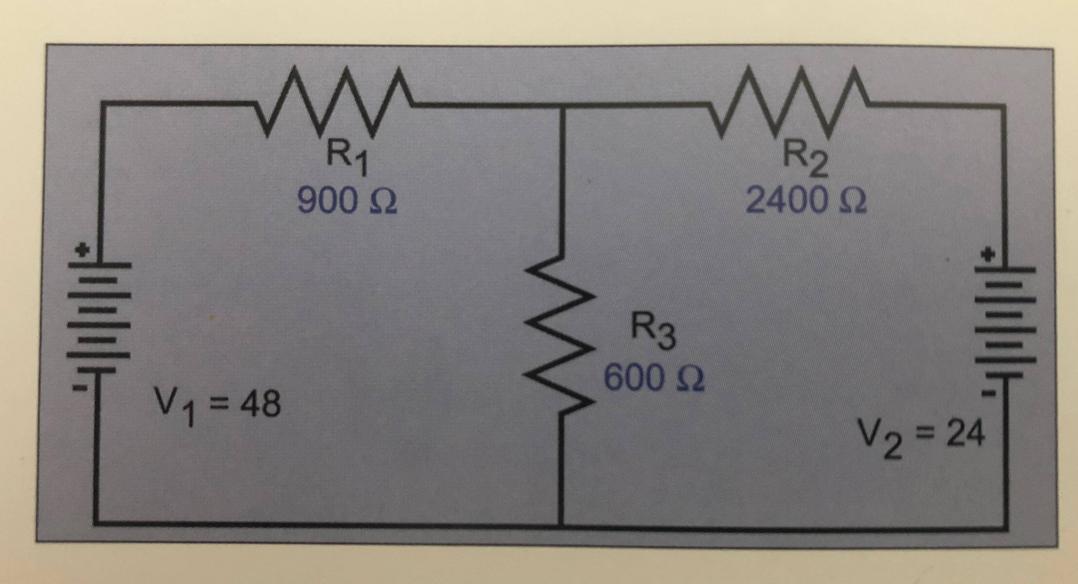
Here is the circuit:

Two Loop Circuit

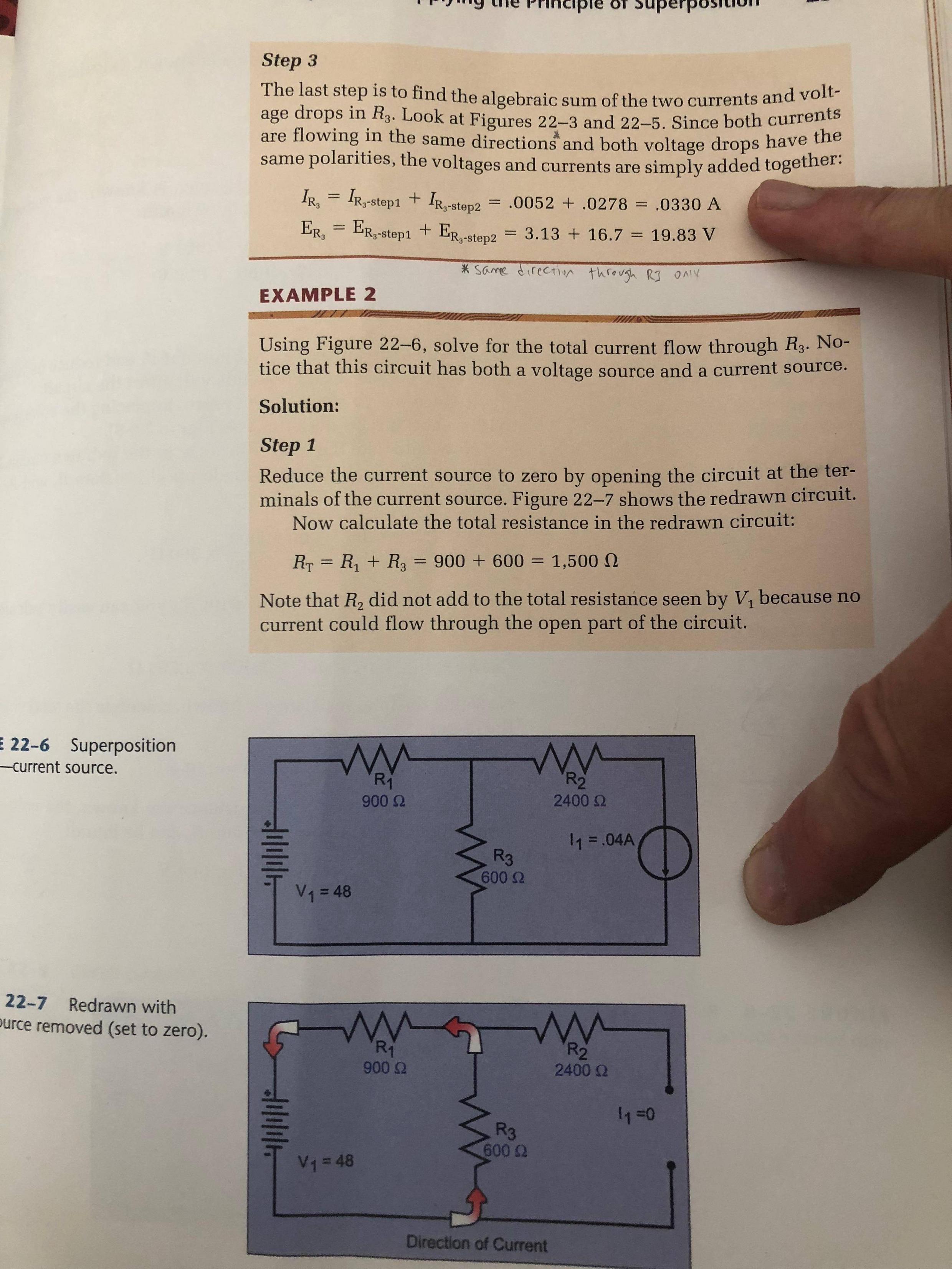
Here is the page (figure 22-6) where they introduce a seemingly arbitrary value for the current source I1 of 0.4A where the 24v battery would normally be. That value is used repeatedly to derive the total circuit voltage on the following pages. (They actually use the inserted value of 0.4 (p263) to derive the values that add up to 0.4 (p265). (Lovely example of circular reasoning and bad editing.)

The values I derived for the combined circuit are as follows, with a positive number denoting flow from the direction of the 48v battery (right hand) and a negative number denoting flow from the direction of the 24 volt battery (left hand). R3 has both flows travelling together in the same direction.

Total Combined Values : E, I, R

  • R1: 28.17 V, 0.031 A, 900 ohms
  • R2: -4.17 V, -0.002 A, 2400 ohms
  • R3: 19.83 V, 0.033 A, 600 ohms

enter image description here

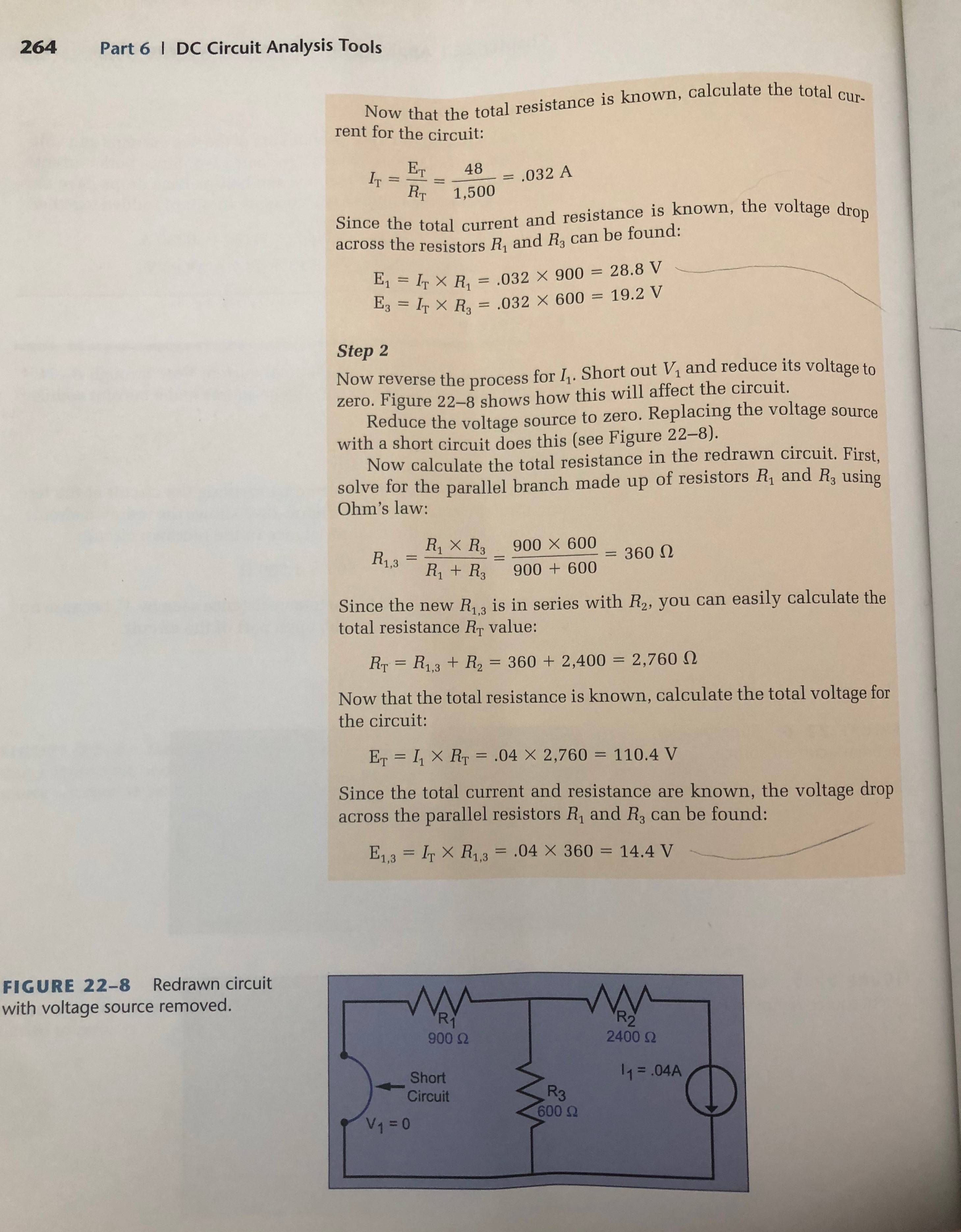
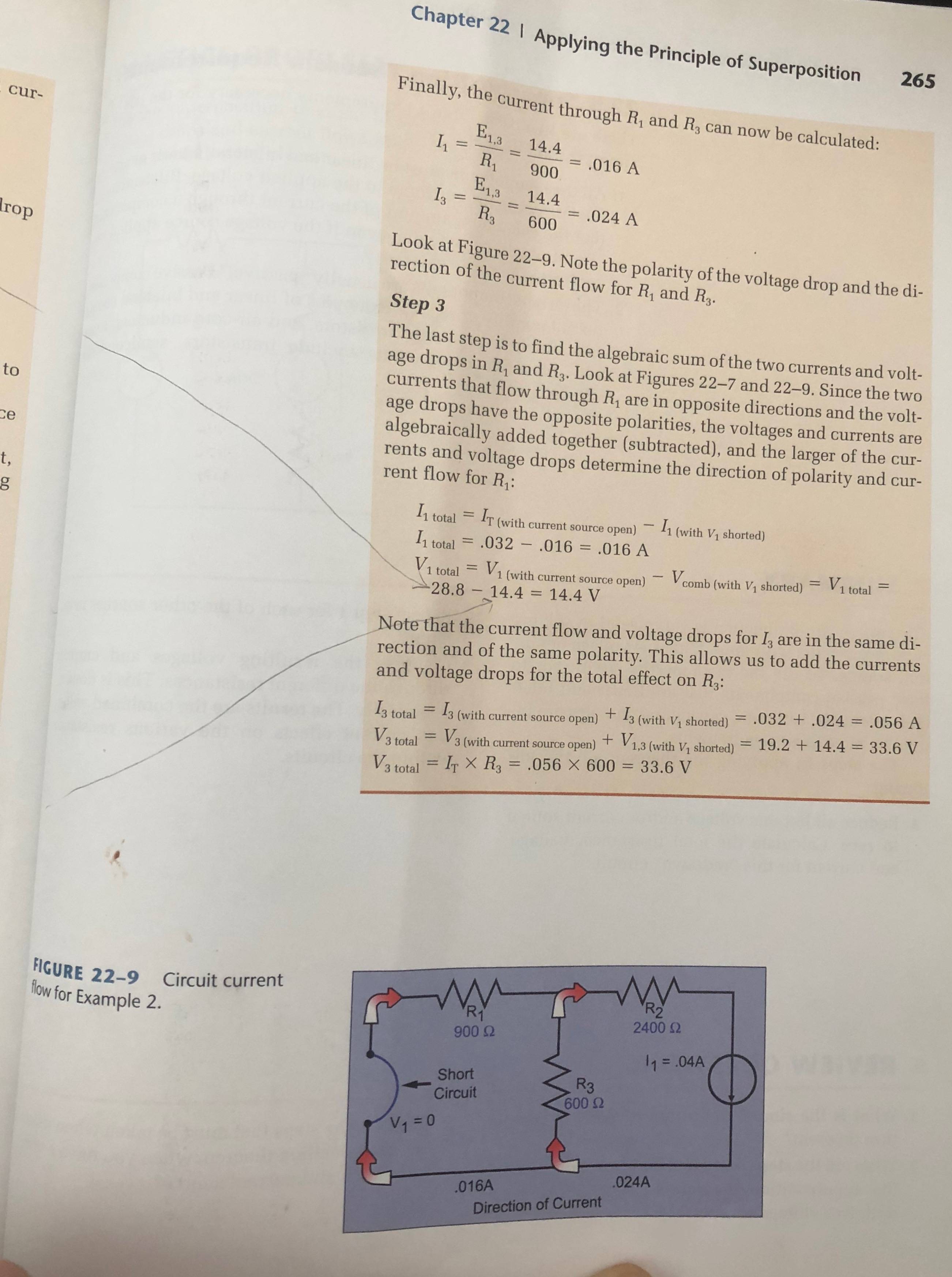
Here are the rest of the pages, to show what the book is trying to teach:

p264

p265

\$\endgroup\$
1
  • \$\begingroup\$ Comments are not for extended discussion; this conversation has been moved to chat. \$\endgroup\$
    – Voltage Spike
    Commented Jun 2, 2020 at 21:36

3 Answers 3

1
\$\begingroup\$

I also got same values for voltage and current for R3, so your calculations are correct for the first picture.

The second picture with the current source is completely different example that has nothing to do with the firat example. Since that example has a current source, it takes a different approach to solve that.

\$\endgroup\$
5
  • 1
    \$\begingroup\$ It's the same example circuit. It is the part that comes AFTER superposition "solves" the circuit. You short out the second source, or something. The book isn't very clear on what/why it does what it does. But it starts out as the same circuit. \$\endgroup\$
    – Russ Bain
    Commented May 25, 2020 at 21:23
  • \$\begingroup\$ I added the next two pages to the post for context. \$\endgroup\$
    – Russ Bain
    Commented May 25, 2020 at 21:31
  • 2
    \$\begingroup\$ No, figure 2-26 is a completely new circuit for example 2. It really has nothing to do with the previous figure with two voltage sources which you correctly solved. \$\endgroup\$
    – Justme
    Commented May 25, 2020 at 22:02
  • \$\begingroup\$ @RussBain Justme is right and you are confused, I believe. It just appears to you that they are supposed to be the same example. They are not. \$\endgroup\$
    – jonk
    Commented May 25, 2020 at 22:19
  • \$\begingroup\$ Yeah, Jonk set me right on that. \$\endgroup\$
    – Russ Bain
    Commented May 27, 2020 at 6:18
1
\$\begingroup\$
  1. "How do I derive the value at I1?"

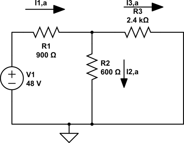
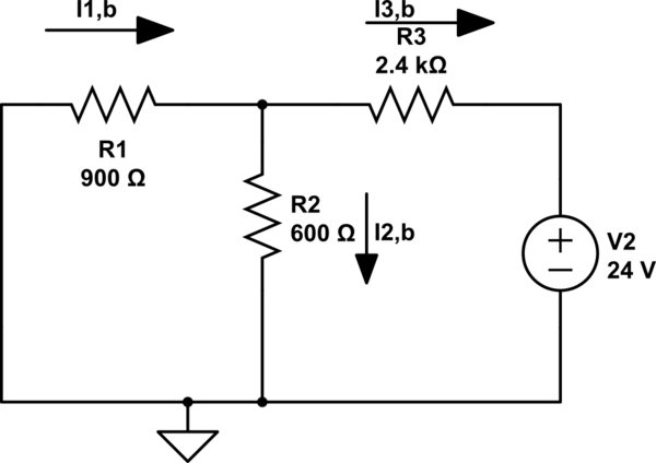
Not sure what is the point of doing the substitution of a voltage supply \$V_2\$ by the current supply \$I_1\$, but to have both circuits having the same currents and node voltages you would need \$I_1\$ to be the current going into \$V_2\$

  1. "What is the correct value at I1 so I can check my work?"

Using a simulator I got that \$I_1=-1.739 mA\$, so the power supply \$V_2\$ is outputting current, notice I am not referring to the current over resistor \$R_1\$ but to the value that would work if you did the substitution you mentioned (which I think is extra work and does not help solve the system).

To solve this using superposition, ignore that supply substitution and do this

To use superposition in this case you would solve the two single supply circuits and just add their currents.

schematic

simulate this circuit – Schematic created using CircuitLab

schematic

simulate this circuit

\$\endgroup\$
3
  • \$\begingroup\$ I1 is 31.3mA and I3 = -1.73mA \$\endgroup\$
    – G36
    Commented May 25, 2020 at 21:11
  • \$\begingroup\$ I was not using \$I_1\$ to refer to the current over resistor \$R_1\$, but to his mention of substituting \$V_2\$ by some current supply \$I_1\$, so the \$I_1\$ I determined is what you call I3. Still, this substitution thing makes no sense as a solving method, not sure where the OP or his book got it from. \$\endgroup\$
    – jDAQ
    Commented May 25, 2020 at 21:17
  • \$\begingroup\$ I added the next two pages to the post for context. \$\endgroup\$
    – Russ Bain
    Commented May 25, 2020 at 21:32
0
\$\begingroup\$

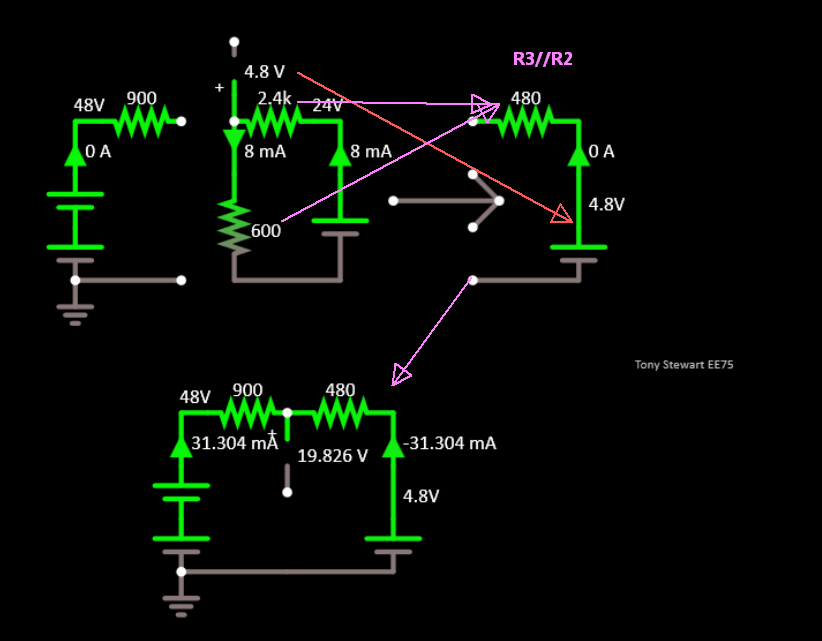
I assume you have read about Thevenin equivalent circuits taking a voltage divider from a voltage source and converting to the equivalent voltage and short circuit current using the parallel resistance.

Also, I assume you can compute a simple voltage divider ratio \$V_3=R_3/(R_3+R_2)*V_2\$ and parallel \$R_{eq} = 1/(1/R_1+1/R_2)\$

For the left side \$I_1\$:

Step 1. Compute equivalent of right side load and voltage for superposition later.

Step 2. then Join and compute \$I_1 = - I_2\$ for the shown ammeter directions.

enter image description here

Interactive simulation with voltage probe and ammeters.

That book is flawed.. I have some tutorials in my profile.

\$\endgroup\$

Your Answer

By clicking “Post Your Answer”, you agree to our terms of service and acknowledge you have read our privacy policy.

Not the answer you're looking for? Browse other questions tagged or ask your own question.