2
\$\begingroup\$

I just read this article, Microcontroller drives piezoelectric buzzer at high voltage through one pin, and it sounds too good to be true.

The schematic:
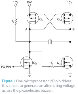
Piezo Driver

Q1 and Q3: BS250 Q2 and Q4: BSS295

This article was published in a well known journal, I guess it must be tested design. But somehow I wonder if there is a catch. So my actual questions are:

why is this circuit not so commonly mentioned on microcontroller forums? What is the catch with this design? Is this a really simple bridge load piezo speaker design that could be used for PWM driven audio amplifiers? Is there an amplifier class (eg class H) that this falls into? Is this too good to be true?

\$\endgroup\$
3
  • \$\begingroup\$ Yuk. That circuit has some serious make-before-break issues. \$\endgroup\$ Commented Nov 30, 2012 at 13:50
  • \$\begingroup\$ @ExcitingProjects To get a fixed frequency off a piezo, why not just use the common and classic "piezo buzzer" that beeps when powered? I'm trying to understand why you (or the author of the article) would want to drive the oscillation from an MCU pin: Is your requirement a speech or music output, or just a single tone? \$\endgroup\$ Commented Dec 1, 2012 at 5:18
  • 1
    \$\begingroup\$ @AnindoGhosh I don't know about article author. I would like a single pin basic quality speech output from a piezo speaker without extra components if possible. Not a fixed frequency. \$\endgroup\$ Commented Dec 1, 2012 at 6:03

2 Answers 2

2
\$\begingroup\$

Looks as if it's not intended as an amplifier, but a maker of loud noises (square waves only) such as for alarm signals.

I suppose you could drive it from a PWM output and it would sort-of work; the only place you could put any filtering would be in series with the speaker itself.

Because the other three transistors are driven by Q2, they cannot switch until after Q2 has switched, and that asymmetrical delay may do bad things at PWM switching frequencies. A little thought will show that Q1 cannot turn off until AFTER Q2 has turned on, for example; creating a momentary short circuit across the PSU...

So my verdict would be: it's fine for alarms, but needs more analysis or testing before serious use in PWM applications.

\$\endgroup\$
1
\$\begingroup\$

A clever but unrelaible design depends on phase shift of piezo device, ratiometric resistor values and ratio metric different N,P FET thresholds. 1.2V, 1.8V Not very reliable. with component variances and using almost obsolete FETs with unknown Piezo capacitance. Perhaps may be possible in mass production buzzers.

I prefer stable Pierce gate NAND gates oscillators for gated self resonant mode. Cheaper and more stable.

This design is not for speakers or related to PWM

\$\endgroup\$

Your Answer

By clicking “Post Your Answer”, you agree to our terms of service and acknowledge you have read our privacy policy.

Not the answer you're looking for? Browse other questions tagged or ask your own question.