0
\$\begingroup\$

I have a base system that runs on 3-AA batteries which it regulates to a system voltage of 3.3V. I want to interface that system to measure a 4-20mA sensor. For the sake of argument, lets say that sensor has a minimum voltage requirement of 8 - 30V. To my slight embarrassment, in my many years of working with sensors, this is my first foray into this 4-20mA business, so I have some questions, and I'm hoping the community can help me clear them up and avoid common pitfalls.
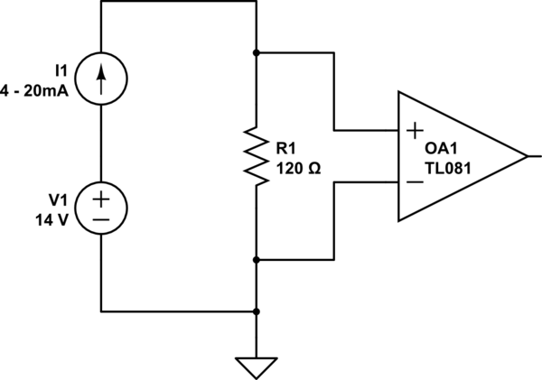
schematic

simulate this circuit – Schematic created using CircuitLab

I've been reading up on working with 4-20mA, and I drew the above schematic as a representative data acquisition hookup. One of the things I've read is that ground loops are a gotcha with these types of sensors. Given that my system is battery operated, is this something that it's essentially immune to?

Given that I'm going to have to throw a boost converter into the system to get up to something like 14V (somewhat arbitrary, but high enough to make sure the sensor gets a voltage that is in its operating range, after voltage drops across my shunt resistor), for a variety of reasons, I want to supply that boost circuit from my 3.3V output buck/boost switching regulator. So my block diagram starts looking something like this (everything here is battery voltage ground referenced, and there's no earth ground in my system). Does everything seem copacetic here?
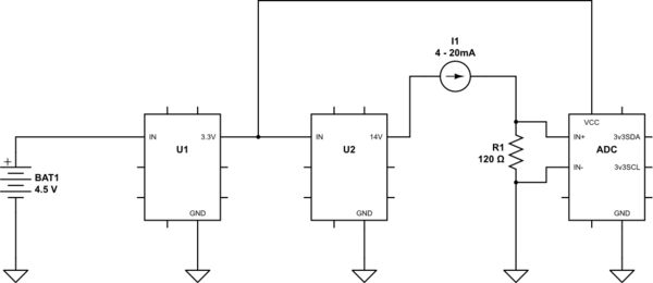
schematic

simulate this circuit

... and finally, my transducer datasheet shows a picture that looks like this: enter image description here
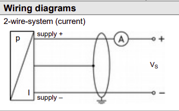
I'm not sure what to make of the grounded shield in that picture. Does that imply anything needed to be done electrically with respect to the shield at the connection point to my system?

Update (Alternative block diagram):
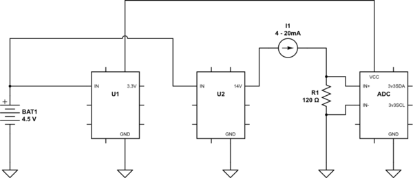
schematic

simulate this circuit

\$\endgroup\$
2
  • \$\begingroup\$ Do I understand correct, that you want to turn an external 4-20mA to a linear corresponding voltage by means of the ADC and R1? If so i am not quite sure what you first figure depicts. \$\endgroup\$ Commented Jun 10, 2020 at 4:15
  • \$\begingroup\$ yes, that's right... the first picture just represents a notional analog front-end for wiring up to the 4-20mA transducer. \$\endgroup\$
    – vicatcu
    Commented Jun 10, 2020 at 11:54

1 Answer 1

1
\$\begingroup\$

In answer to your question, the ungrounded supply will not contribute to ground issues, but there might be other connections to your system.

If you draw 20mA at 14V it will Likely draw close to 100mA from the 3.3V supply. Other than that it looks fine, assuming it’s a 2-wire P to I transmitter.

Shielding depends a lot on the exact setup and where, if anywhere, the circuit has an earth connection.

\$\endgroup\$
2
  • \$\begingroup\$ Thanks! Do you think I'd be better off connecting the boost circuit directly to the battery controlled by an enable control signal? Regarding other comments, it's essentially a closed system (no external electrical connections, plastic enclosure). \$\endgroup\$
    – vicatcu
    Commented Jun 10, 2020 at 11:58
  • \$\begingroup\$ I guess at 4.5V, it would draw about 70mA, which is a 30% power savings. \$\endgroup\$
    – vicatcu
    Commented Jun 10, 2020 at 12:07

Your Answer

By clicking “Post Your Answer”, you agree to our terms of service and acknowledge you have read our privacy policy.

Not the answer you're looking for? Browse other questions tagged or ask your own question.