3
\$\begingroup\$

Me and my team are developing an LED light controller for street lighting applications.

We are trying to measure current draw, voltage and power consumption using Allegro's ACS71020 but the readings don't seem to make any sense. We have achieved a successful communication using I2C, since we can write and read multiples registers. For example, we changed the default slave address to 0x45, and to do that we had to write the customer code to a specific register, and then set 0x45 address (which involves another write operation). After that, we read the register that holds the I2C slave address and it appears changed. So we take from that that we're reading and writing successfully.

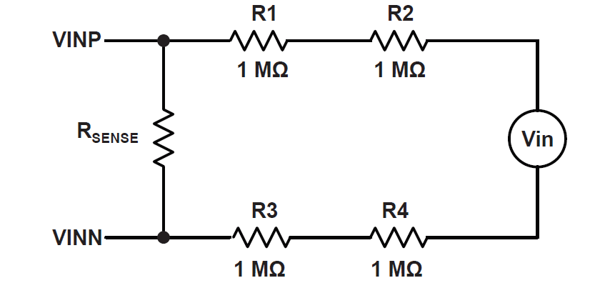
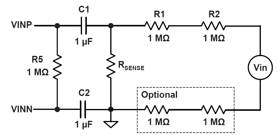
We're testing this IC using the evaluation board ASEK71020KMAB-090B3-I2C. We're using two different step-down circuits (recommended by the chip documentation), which are shown in the schematics attached (let's call circuit 1 to the purely resistive one, and circuit 2 to the one with capacitors).

Circuit1

Circuit 2

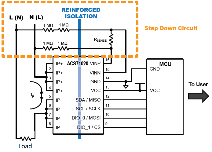
Here's another schematic showing the hardware setup, where the step-down circuit can be circuit 1 or circuit 2 (the image shows circuit 1).

Acs connection schematic

We're working with a 220V/50Hz power source. For the circuit 1 we're using an Rsense of 2.2k and for the circuit 2 a 1.8k resistance. From these values we have calculated a Full Scale Voltage of 500V for the first circuit and 610V for the latter, using the formulae on the documentation. We used 90A as the Full Scale Current. After reading the corresponding register (0x20) for the Vrms and Irms readings we use the following code to decode the reading.

v=(RXData[1]*256+RXData[0])/0x8000 ;
i=(RXData[3]*256+RXData[2])/0x4000 ;

Where RXData is an array that stores the received bytes from the I2C reading operation in the order specified by the acs71020 user guide.

To test the ACS71020, we're using an incandescent lightbulb as the target load. Measuring its current draw, we see that it consumes 360mA @220V. The results using either the capacitive circuit or the resistive circuit are pretty similar. When the bulb is off we get Vrms = 224V, and i = 3.1A ; and when it's on Vrms = 224 and i = 2.8A.

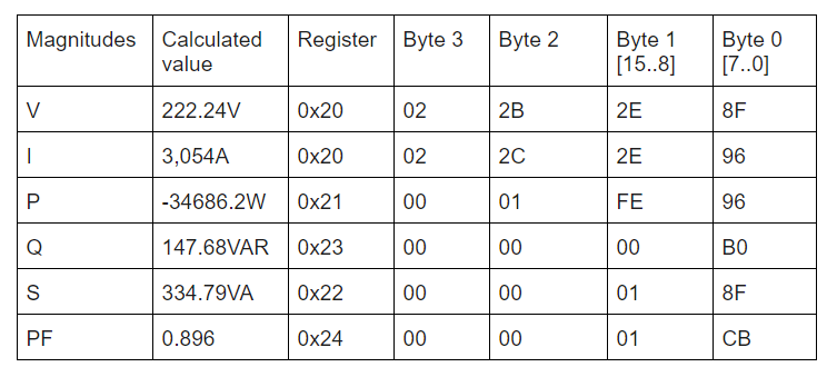
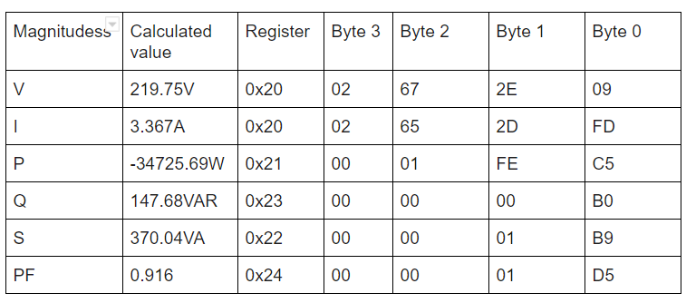
The next two tables contain the data obtained from the chip:
Table 1: The lightbulb is off

lightbulb is off

Table 2: The lightbulb is on

lightbulb is on

Here's the C code we're currently using to get the readings:

float acs71020_get_voltage(){
    float aux_v=0;
    
    acs71020_read(REG_IRMS_VRMS);
    aux_v=((float)(RXData[1]*256+RXData[0]))/0x8000;
    aux_v=aux_v*(FULL_SCALE_V);
    
    
    return aux_v;
}

float acs71020_get_current(){
    float aux_i=0;
    float aux_2=0;

    acs71020_read(REG_IRMS_VRMS);
    aux_2=(RXData[3]&0x7f)*256;
    aux_i=(aux_2+RXData[2])/0x4000;
    aux_i=aux_i*(FULL_SCALE_I);

    return aux_i;
}

Those are for current and voltage, the procedures for power and power factor are similar.

We believe something is wrong with the setup in the chip. We couldn't find any examples of the chip configuration settings. Current state of the configuration registers:

0B:

raw values: 00 20 00 00
by fields:
qvo_fine = 0
sns_fine = 0
crs_fine = 0
iavgselen = 1

0C:

raw values: 00 00 00 3C
by fields:
rms_avg_1 = 60 (decimal)
rms_avg_1 = 0

0D:

raw values: 00 1F E0 00
by fields:
pacc_trim = 0
ichan_del_en = 0
chan_del_sel = 0
fault = 255 (decimal)
fitdly = 0
halfcycle_en = 0
squarewave_en = 0

0E:

raw values: 00 08 20 00
by fields:
vevent_cycs = 0
vadc_rate_set = 0
overvreg = 32 (decimal)
undervreg = 32 (decimal)
delaycnt_sel = 0

0F:

raw values: 00 00 03 14
by fields:
i2c_slv_addr = 69 (decimal, or 0x45)
i2c_slv_addr = 1
dio_0_sel = 0
dio_1_sel = 0

What are we doing wrong?

I hope to get some help! Thanks in advance

\$\endgroup\$
12
  • \$\begingroup\$ "When the bulb is off we get Vrms = 224V, and i = 3.1A ; and when it's on Vrms = 224 and i = 2.8A." - but the tables say I = 3.054A and 3.367A. ??? \$\endgroup\$ Commented Jul 1, 2020 at 4:53
  • \$\begingroup\$ Trim registers are set to 0, and slave address is locked to 69 which is a non-standard value. Is the board new, or has it been used before? Did you reprogram any of the EEPROM registers? Can you show us the values in the shadow registers? \$\endgroup\$ Commented Jul 1, 2020 at 6:14
  • 1
    \$\begingroup\$ I was having problems with my ACS71020 and stumbled across your question, would you mind posting here the code you are using to comunicate with de ACS71020? I'm using the SPI 30amp model with light bulb attached to it, and when i try to make a current and voltage reading from the register 0x20 the only thing i get is random values of voltage, ranging from about 20 to 290 volt, when it should be always around 230Volt the current is always set on 0Amps. Am i making measurements too fast or is it something with the registers? \$\endgroup\$ Commented Jul 31, 2020 at 23:29
  • 1
    \$\begingroup\$ Russel Mcmahon i've made a question topic in another section do you mind watching it? electronics.stackexchange.com/questions/514409/… \$\endgroup\$ Commented Aug 1, 2020 at 18:44
  • 1
    \$\begingroup\$ Are you able to explain your thought process while making the code to read active power? why do you subtract it by 0x2000 when it's negative. same stuff on pfactor bue you subtract it by 0x0800 \$\endgroup\$ Commented Aug 3, 2020 at 14:33

3 Answers 3

2
\$\begingroup\$

Ok, I've done some testing and i've found out that as stated in the cover of the datasheet the power supply of your ASEK71020KMAB-090B3-I2C and your Micro-controller unit needs to be isolated. You should be able to test this out by powering it all from a laptop using only it's battery (it shouldn't be charging otherwise it wont be isolated).

This fixed my issues with random readings and it should fix yours also. If not you ought to check the code to convert the binary number into a float or integer. In your case your IPr or fullscale current should be 90Amps you should check that out too.

You should also check the "qvo_fine" in register 0x0B/0x1B As stated in the datasheet page 22


qvo_fine Offset adjustment for the current channel.
This is a signed 9-bit number with an input range of –256 to 255. With a step size of 64 LSB, this equates to an offset trim range of –16384 to 16320 LSB, which is added to the icodes value. The trim is implemented as shown in Figure 14. The current channel’s offset trim should be applied before the gain is trimmed. “qvo_fine” is further described in Table 1.


In a more definitive project you need to buy a transformer or a ready made isolated power supply that can power all your electronics.

\$\endgroup\$
5
  • 1
    \$\begingroup\$ "Obvious in retrospect" :-) - it's annoying how much time one can spend and then find something like this. Presumably the uC and conversion IC can share the same power supply (ie do not need to be isolated from each other). \$\endgroup\$
    – Russell McMahon
    Commented Aug 3, 2020 at 0:55
  • 1
    \$\begingroup\$ WARNING: IC's like this offer high claimed isolation levels - which is true when they are functioning correctly. However, if you grossly overload the internal shunt for the Hall cells so that the IC is incinerated you can get conduction paths from the high voltage input to the electronics. I've had this happen with a battery monitoring Hall current sensor when the load was shorted. This can be "very exciting" and worst case could be fatal. \$\endgroup\$
    – Russell McMahon
    Commented Aug 3, 2020 at 0:56
  • \$\begingroup\$ @diogoferreir Please use the comment system \$\endgroup\$
    – Voltage Spike
    Commented Aug 3, 2020 at 17:38
  • 1
    \$\begingroup\$ @VoltageSpike since i dont have 50rep i cannot comment on others questions or answers (this system isn't smart at all) \$\endgroup\$ Commented Aug 3, 2020 at 17:44
  • 1
    \$\begingroup\$ That is by design, the site does not let people comment until they prove they are useful contributors. The site is designed to not give people privileges until they have reputation. This is a Q&A site so discussion is frowned on, if you want to discuss then use the chat \$\endgroup\$
    – Voltage Spike
    Commented Aug 3, 2020 at 17:47
2
\$\begingroup\$

We finally found the problem: At some point, we accidentally overwrote the trim registers. We got extra ACSs (but 30A version this time) and it is working reasonably well. Thank you!

As for the code: We're using TI's MSP432 as MCU, and we're using TI DriverLib to get the I2C working. As for the "decoding" code, here it is:

float acs71020_get_voltage() {
    float aux_v = 0;

    acs71020_read(REG_IRMS_VRMS);
    aux_v = ((float)(acs_RxData[1] * 256 + acs_RxData[0])) / 0x8000;
    aux_v = aux_v * (FULL_SCALE_V);

    return aux_v;
}

float acs71020_get_current() {
    float aux_i = 0;

    acs71020_read(REG_IRMS_VRMS_PROM);
    aux_i = ((float)(acs_RxData[3] * 256 + acs_RxData[2]));
    aux_i = aux_i * (FULL_SCALE_I) / 0x4000;

    return aux_i;
}

float acs71020_get_actpwr() {
    float aux_pwr = 0;

    acs71020_read(REG_ACTPWR_PROM);
    if (acs_RxData[2] & 0x01) { //Es negativo
        aux_pwr = (float)(acs_RxData[1] * 256 + acs_RxData[0]) - 0x20000;
    }

    else { //Es positivo
        aux_pwr = ((float)(acs_RxData[1] * 256 + acs_RxData[0]));
    }

    aux_pwr = aux_pwr * (FULL_SCALE_V * FULL_SCALE_I) / 0x8000;

    return aux_pwr;
}

float acs71020_get_apppwr() {
    float aux_pwr = 0;

    acs71020_read(REG_APPPWR);
    aux_pwr = ((float)(acs_RxData[1] * 256 + acs_RxData[0]));
    aux_pwr = aux_pwr * (FULL_SCALE_V * FULL_SCALE_I) / 0x8000;

    return aux_pwr;
}

float acs71020_get_reapwr() {
    float aux_pwr = 0;

    acs71020_read(REG_REAPWR);
    aux_pwr = ((float)(acs_RxData[1] * 256 + acs_RxData[0]));
    aux_pwr = aux_pwr * (FULL_SCALE_V * FULL_SCALE_I) / 0x8000;

    return aux_pwr;
}

float acs71020_get_pfactor() {
    float aux_pfactor = 0;

    acs71020_read(REG_PFACTOR);
    if (acs_RxData[1]&0x04) { //Es negativo
        aux_pfactor = (float)(acs_RxData[1] * 256 + acs_RxData[0]) - 0x0800;
    }

    else { //Es positivo
        aux_pfactor = ((float)(acs_RxData[1] * 256 + acs_RxData[0]));
    }

    aux_pfactor = aux_pfactor * (FULL_SCALE_V * FULL_SCALE_I) / 0x800;

    return aux_pfactor;
}

I hope you find it useful!

\$\endgroup\$
1
\$\begingroup\$

Nearly a year on and hitting the same issues. Can't comment (insufficient reputation) but can add this little nugget..

When you've checked that your supply is isolated, when you know your calibration is back to factory, when you have clean I2C comms and everything looks good but for the numbers coming back to you on the voltage?

Check your other connections. For me, the ACS was connected to a microcontroller devkit board which was in turn connected via USB for programming and monitoring back on my PC. A PC with a standard AT supply which, you guessed it, can pin your USB ground to neutral.

After two days of bashing my head against a wall, ran it up with a laptop just in case and it worked perfectly.

\$\endgroup\$

Your Answer

By clicking “Post Your Answer”, you agree to our terms of service and acknowledge you have read our privacy policy.

Not the answer you're looking for? Browse other questions tagged or ask your own question.