0
\$\begingroup\$

Edit: I did a dumb-dumb. I got the emitter and collector mixed up on both transistors. Now it works.

What I'm trying to accomplish:

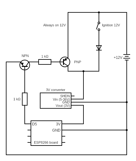
I'm planning to run a ESP8266 microcontroller in my car. The ESP runs off a 3V converter. I want it to turn on when turning the ignition on, but when ignition is turned off I want the ESP to decide when to turn off the curcuit. (I want to save some data etc. before shutdown) I want as little power draw as possible (or none) when it is shut down.

Current sollution attempt:

schematic showing sollution with two transistors

After some suggestions from others, I attempted to set up the circuit as shown in the schematic, using two transistors. The NPN transistor is a BC547 and the PNP is a BC557. The 3V converter with everything connected draws about 25mA at 12V. With the transistors in place the numbers are roughly 11.5V 30mA.To keep the circuit on the ESP outputs 3V on the D5 pin. However, there are problems:

  • When the circuit is supposed to be off there is still 4V on the PNP transistor emitter pin.
  • When powered through the transistors the ESP does not turn on. I should measure what I'm getting out of the 3V converter, but I'm currently not at home so can't do that right now.

Help?

  • Is the attempted sollution the best way to go or would it be simpler/better using a relay or any other sollution instead?
  • My knowledge of transistors is limited even after trying to read up a bit. I must be doing something wrong, but what? I am trying to learn, so just giving me pointers and letting me do some of the work is fine. (Also, I'm as lazy as anyone, so no complaints about complete sollutions either ;) )

Thank you!

\$\endgroup\$
5
  • \$\begingroup\$ If you have 4 volts on the emitter then you must also have 4 volts on your "always ON 12 volt" line. If in fact you mean "collector" then fix your question. \$\endgroup\$
    – Andy aka
    Commented Jul 15, 2020 at 10:03
  • \$\begingroup\$ If i measure between collector and GND the multimeter shows 12V. If I measure between emitter and GND i get 4V. However, as someone else pointed out to me a moment ago, the current leaking through when the transistor is "switched off" is probably in the nA range so it might just be the (cheap) multimeter. \$\endgroup\$ Commented Jul 15, 2020 at 10:22
  • 1
    \$\begingroup\$ Listen to me: the emitter in your circuit is connected to the always-on-12 volts hence you are contradicting yourself. \$\endgroup\$
    – Andy aka
    Commented Jul 15, 2020 at 10:24
  • \$\begingroup\$ You are completely right! Facepalm moment! I mixed up collector and emitter. I need to check what way I connected it on the lab deck. I'll be home within the hour. Will be updating the question. Thank you! \$\endgroup\$ Commented Jul 15, 2020 at 10:31
  • \$\begingroup\$ Yep, it was the transistors mounted the wrong way. Now it works fine. Thank you again. Sometimes all a problem needs is a fresh set of eyes. :) \$\endgroup\$ Commented Jul 15, 2020 at 12:14

1 Answer 1

1
\$\begingroup\$

If you have 4 volts on the emitter then you must also have 4 volts on your "always ON 12 volt" line. If in fact you mean "collector" then fix your question.

You are completely right! Facepalm moment! I mixed up collector and emitter. I need to check what way I connected it on the lab deck. I'll be home within the hour. Will be updating the question. Thank you!

Yep, it was the transistors mounted the wrong way. Now it works fine. Thank you again. Sometimes all a problem needs is a fresh set of eyes.

A little bit of interrogation usually sorts many problems out. Good luck.

BJTs are a bit bi-directional (they are NPN or PNP for example) and, can be swapped around (with care) but one of the drawbacks is that current gain is greatly reduced and this is the likely problem.

\$\endgroup\$

Your Answer

By clicking “Post Your Answer”, you agree to our terms of service and acknowledge you have read our privacy policy.

Not the answer you're looking for? Browse other questions tagged or ask your own question.