0
\$\begingroup\$

I'm trying to build a simple water level detector using BC557 PNP transistor (there's already a similar question here but doesn't solve my problem...)

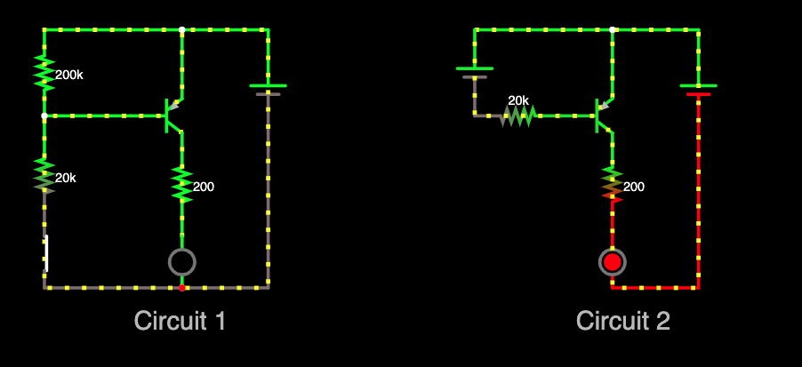
Circuit 1 below is what I'm thinking to build based on the standard biasing of PNP circuits (Circuit 2) as there's only 1 power source available. However, without a power source to reverse bias Emitter, I'm not able to have a Collector current. I think I'm doing something wrong here as it should work based on this for example. I can simulate an emitter current in Circuit 1 but no matter what resistors I use on the Emitter end (using 20k and 200k here) I cannot get a Collector current. Any idea what I'm doing wrong? This is my simulation.
4

\$\endgroup\$
2
  • \$\begingroup\$ Try this tinyurl.com/y8gbft5w \$\endgroup\$
    – D.A.S.
    Commented Feb 27, 2021 at 5:44
  • \$\begingroup\$ you can do this 3V too and adjust R values \$\endgroup\$
    – D.A.S.
    Commented Feb 27, 2021 at 5:57

1 Answer 1

1
\$\begingroup\$

Problem: Learning curve error with Falstad drawing.

You had Red Dot below LED indicating it was not a junction (disconnected) So shink line and add another wire as in my comment link fixed.

But you had 12V with a pretty big LED current which only uses a couple volts which is very inefficient. So I assumed 20mA here.

Also remember to reduce hFE to 10% of maximum when using a switch.

\$\endgroup\$

Your Answer

By clicking “Post Your Answer”, you agree to our terms of service and acknowledge you have read our privacy policy.

Not the answer you're looking for? Browse other questions tagged or ask your own question.