0
\$\begingroup\$

I've been trying to get the Microchip RN4678 bluetooth module working so I can start having fun with it, but I'm having very very limited success. The problem is the fact that the datasheet states:

To enter Command mode, type $$$ into the terminal emulator. Once RN4678 enters Command mode, it sends the string CMD via the UART to indicate the start of Command mode session.

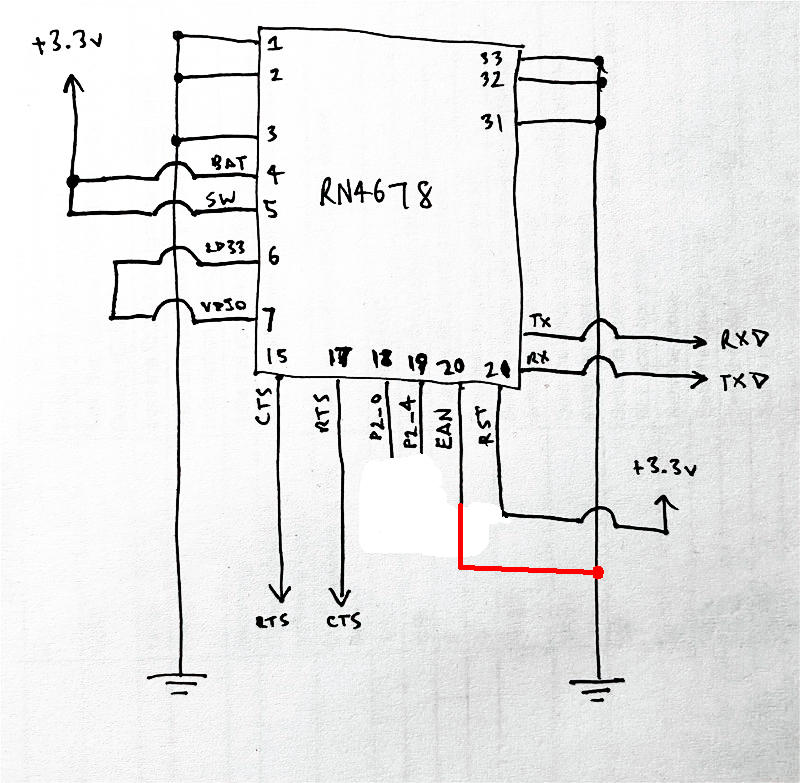
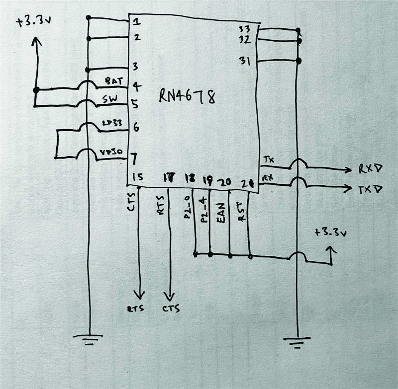
I'm doing exactly that, along with every variation and am getting no response. Here's my setup. First things first I've got it plugged into a breadboard like this:

enter image description here

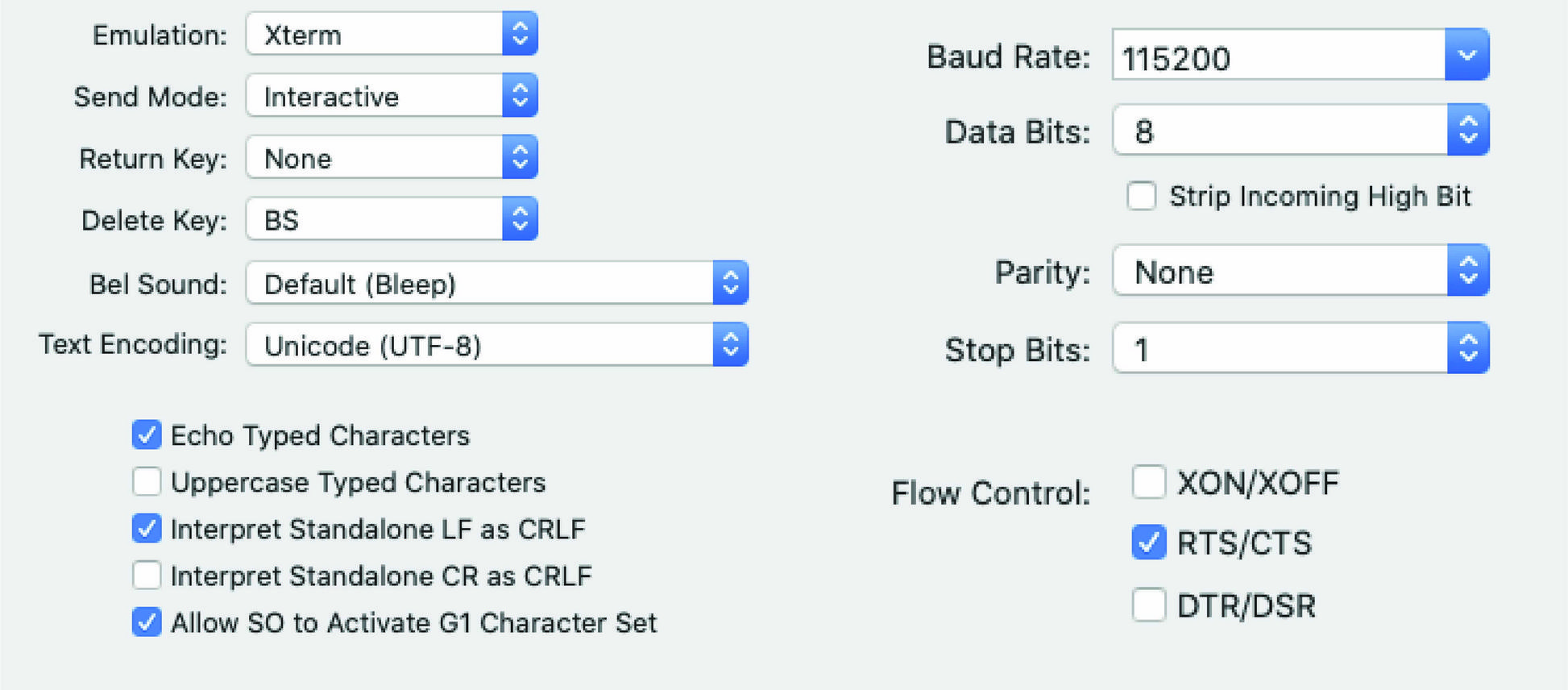
I'm using a stock TTL programmer based around the FTDI232R, and it's all being controlled and monitored from the OSX program Serial. Here's the settings I'm using in serial.

enter image description here

Observations from my troubleshooting so far:

  1. The chip itself is working fine. I can connect to it through the mBIoT utility iPhone app, and it sends and transmits data from phone to computer and vice versa fine, so I know the module isn't dead.
  2. The modules CTS pin doesn't get pulled low unless there is a paired connection. When my phone is connected I can pipe data through the RN4678 from computer to phone with hardware flow enabled just fine, but as soon as I disconnect my phone, I cannot talk to the module at all.
  3. I've looked into the option of the modules "fast-mode" being activated by default, where the original "$$$" command doesn't work, and instead you have to pull a specific pin low. So I went around, and pulled each pin low individually and had no success.

Right now it just feels like theres a hidden pin in there that needs to be pulled in some sort of direction. I've had a good look at the Pictail Reference design for this module and I'm faily sure I haven't missed any pins.

If this is ringing any bells for anyone, or if you have any ideas I should try I'd really love your help. Here's the corresponding Datasheet and User Guide for this module.

\$\endgroup\$
0

3 Answers 3

1
\$\begingroup\$

I worked with RN4870 and it worked just fine for me after 2 months of debugging. It just takes time. When I did it, I didn't connect CTS or any other pin. I just had Vbat to 3.3V, Gnd, tx and rx. Rst is internally pulled high. Don't mess with it.

I see that you are sending 'LF' after your command. When sending that command you should not send LF or CR. The chip doesn't interpret it as a command for data mode. Deselect LF and try sending $$$. I had this problem when I was working on this. Let me know if this works.

\$\endgroup\$
5
  • \$\begingroup\$ Appreciate your answer! I've followed your advice, now I'm getting a reply! But it's just a random character. With the recommended settings it looks like a "<tab>r" \$\endgroup\$
    – ezra_vdj
    Commented Sep 3, 2020 at 2:20
  • \$\begingroup\$ Ok, so I found out if I slow the baud rate right down I can get the sent string returned back to me. From 4800 onwards, the string starts corrupting on return, all the way till 115200, where the string is completely ruined. \$\endgroup\$
    – ezra_vdj
    Commented Sep 3, 2020 at 3:26
  • \$\begingroup\$ What is the baud rate that you are using? The default baud rate is 115200. You should set the baud rate to 115200. Now send $$$ without LF or CR. what is the exact response that you are getting? it should be "cmd" If you want echo, send '+' after setting the chip in command mode. Can you share the screenshot of your serial terminal? I can understand better. \$\endgroup\$
    – varun
    Commented Sep 3, 2020 at 19:46
  • \$\begingroup\$ I’m sorry to say I ended up switching to the RN4871 and it’s working so good. I think I may have fried my RN4678’s, but when I tried your advice I definitely started getting a response but it was garbled as. Thanks for your help! \$\endgroup\$
    – ezra_vdj
    Commented Sep 7, 2020 at 6:40
  • \$\begingroup\$ No worried .. Glad to be of help. Good luck \$\endgroup\$
    – varun
    Commented Sep 8, 2020 at 20:40
1
\$\begingroup\$

P2_0 and P2_4 should be pulled high as you have in your schematic (but not necessary as the datasheet claims there are internal pull-ups), but the EAN pin (#20) needs to be pulled to GND for "Normal Operation / Application Mode". Refer to Table 2-1 in the datasheet. Your configuration where all lines are pulled high is undefined.

\$\endgroup\$
0
\$\begingroup\$

In the manual the pin "SW_BTN" doesn't has to be connected and is stated "default: disabled". But in reality this input has to be set to BAT_IN (3,3V) permanentely if the module should work!!

As stated above the EAN Pin has to be pulled to GND to enable "normal operating mode / command mode". The configuration in the following modified drawing is working fine (without the option to flash new firmware - in this case the signals P2_0, P2_4 & EAN need another signal configuration). enter image description here Afterwards the module (RN4678) is running in "normal communication mode" but can be switched to command mode by sending "§§§CR" (CR = one sign) answered by "CMD> CRLF" (CRLF = two signs) and so on ...

\$\endgroup\$

Your Answer

By clicking “Post Your Answer”, you agree to our terms of service and acknowledge you have read our privacy policy.

Not the answer you're looking for? Browse other questions tagged or ask your own question.