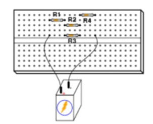
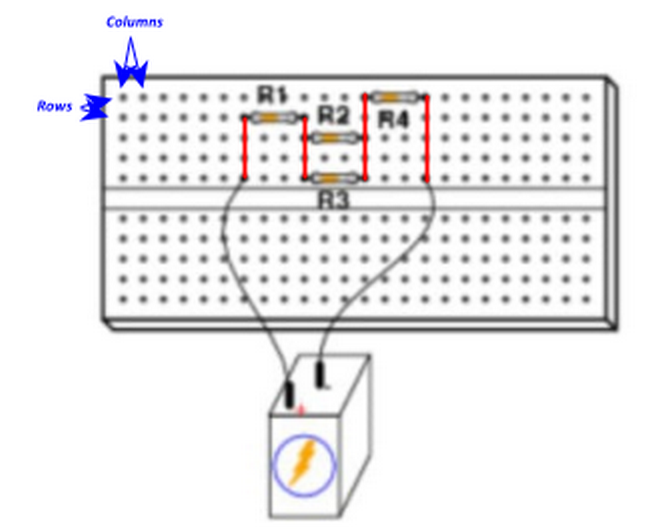
I am asked to find the schematic diagram of the following breadboard configuration:
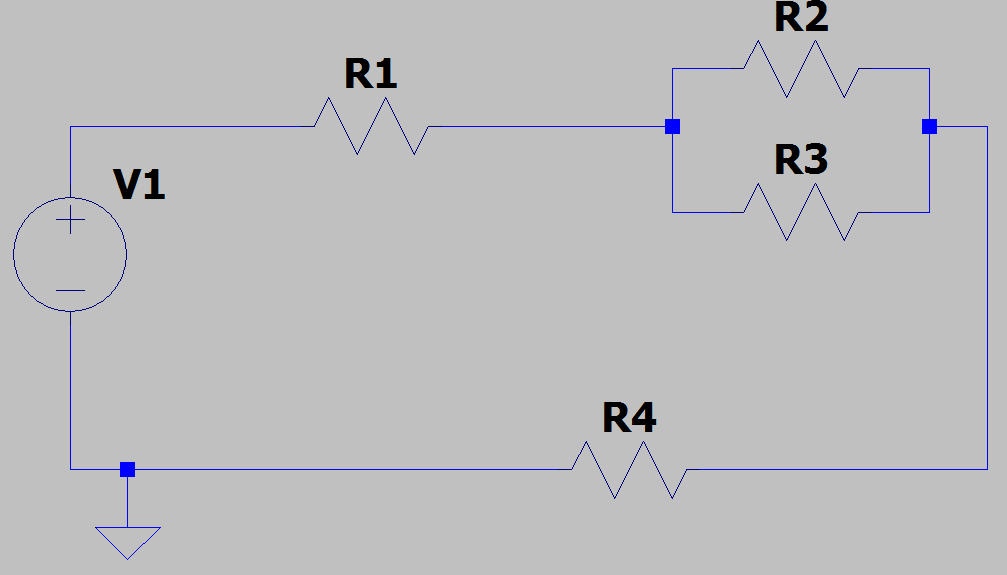
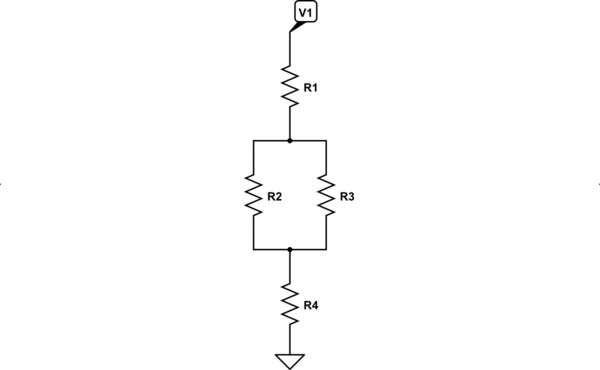
What I understand is that the current flows from R1 to R4, as supplied by the voltage. Since the current seems to split into the two resistors after R1, I assumed that there should be a node. After that, I placed R4 as connected in series with the exit node of the parallel circuits.
Is the following schematic correct?


