0
\$\begingroup\$

I want to get into electronics and I am interested in creating oscillator circuits. In one experiment I wanted to use an Opamp for an oscillator and I am now stuck with the power requirements of it. I could use two batteries to get V+ and V- but I wondered, if it was possible to use an USB power adapter instead.

In order not to fry my one TL064CN chip with its 4 opamps, that needs VCC+ and VCC-, I want to ask what I have to take care of. I learned, that I could create a voltage devider with two resistors, where the connection between the resistors becomes the GND reference and the first resistor the positive rail and the second one the negative one. Would such a simple voltage divider using two reistors be enough?

\$\endgroup\$
3
  • 1
    \$\begingroup\$ No, the minimum recommended supply for the TL084 is +/- 5V and the USB supply only gives you +5. You'll need to generate the -5 from it somehow. \$\endgroup\$
    – Finbarr
    Commented Nov 14, 2020 at 0:14
  • \$\begingroup\$ Resistor divider will work very badly. You can use one of the 4 op amps to create a rail splitter. Feed the resistor divider output to an opamp which is set up as a buffer. It's output will give you +2.5V as a virtual ground (can sink/source only a few mA, but regulation will be good). Or alternatively, you can generate a -5V using a NE555 and some capacitors and diodes... by inverting the +5V (and then probably regulate it with a zener) \$\endgroup\$
    – Indraneel
    Commented Nov 14, 2020 at 0:14
  • \$\begingroup\$ @Indraneel would you maybe have a tutorial how to set up such a rail splitter? I want to learn but I lack many components so the simplest circuits are best. I have no NE555 although I desoldered a NE558 (quad timer) from an old ISA joystic card but have not managed to test it yet. \$\endgroup\$ Commented Nov 14, 2020 at 10:34

1 Answer 1

1
\$\begingroup\$

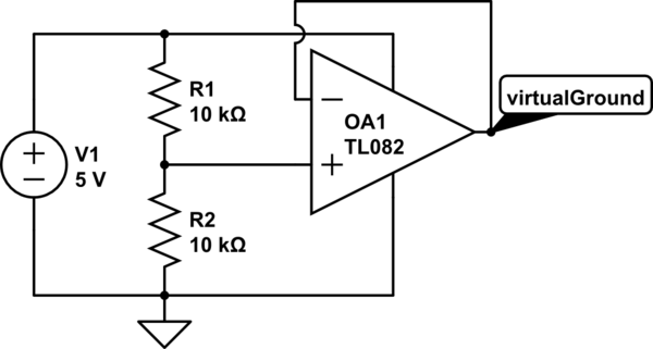
A very simple rail splitter. From the datasheet of TL064 it seems maximum output source/sink current is only about 3 mA (to maintain 2.5 V output at 5 V supply).

schematic

simulate this circuit – Schematic created using CircuitLab

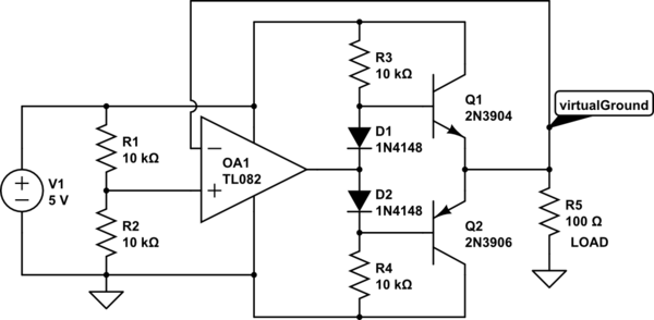
An option to increase output current would be to add a push pull output stage with an NPN and a PNP transistor pair, but that may likely introduce crossover distortion if not designed properly. Here is a very simple push pull output stage.

schematic

simulate this circuit

\$\endgroup\$
0

Your Answer

By clicking “Post Your Answer”, you agree to our terms of service and acknowledge you have read our privacy policy.

Not the answer you're looking for? Browse other questions tagged or ask your own question.