19
\$\begingroup\$

I opened up a really tiny mobile phone charger I have, to see how it is designed. The entire "charger" is integrated into a small 2-pin mains plug, 1 x 1.25 x 0.5 inch, that has an USB socket for the phone's USB charging cable.

I could not find anything that seems to be a transformer anywhere in the circuit, and yet I have tested that it is an isolated 5 volt well-regulated output. The tiny flexible PCB has merely a dozen or so SMD parts, ranging from 0402 to 4516 (metric), plus the connectors at the two ends, for mains and for USB. The SMD parts all have part numbers sanded off.

How do they manage the isolation in these chargers?

Responses to comments: This is a no-name "Hi-Standard USB phone charger, Extra Powerful!" I have just bought in Korea, that is supposed to work with any USB-charged cellphone. They have pictures of a half dozen different cellphones on the box, and a hydra USB cable inside that has mini-USB, micro-USB and some other types of connectors.

I bought it just to see whether it is safe or not. That is why I tested for isolation first.

\$\endgroup\$
8
  • \$\begingroup\$ Are there no parts that look like an SMD inductor, on the board? Also, is this a brand-name charger, or an aftermarket no-name? \$\endgroup\$ Commented Jan 10, 2013 at 11:41
  • 11
    \$\begingroup\$ Can you upload a picture? \$\endgroup\$
    – jippie
    Commented Jan 10, 2013 at 11:43
  • \$\begingroup\$ Any product link to either the phone or the charger? \$\endgroup\$ Commented Jan 10, 2013 at 11:44
  • 1
    \$\begingroup\$ Could we discuss the charger mystery in EE chat? \$\endgroup\$ Commented Jan 10, 2013 at 12:11
  • 1
    \$\begingroup\$ Possible duplicate of this question. \$\endgroup\$ Commented Jan 10, 2013 at 12:16

4 Answers 4

28
\$\begingroup\$

Although the question has provided limited details, this answer presents a somewhat different hypothesis from the standard assumption that there's an inductive coil hidden in there somewhere.

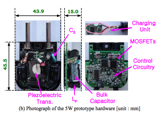
The charger in question possibly uses a Piezoelectric Transformer instead of the magnetic (inductive) transformers usually seen for isolation.

Does the charger looks somewhat like this?

Piezo Transformer power adapter

If yes, the designers have used a Piezo transformer instead of a conventional one. Interestingly, the source of this image is a paper in a Korean academic publication. This makes the hypothesis even more apt.

A piezoelectric transformer designed for Mhz operation, 500 mA secondary current with 5 Volt signals, using Polyvinylidene Fluoride (PVDF) as the piezoelectric medium, could be fabricated as a thick 1210 SMD part. Since the question mentions SMD parts up to 4516 metric i.e. 1806 imperial, one of the largest of those components is probably the piezoelectric transformer providing the isolation as per the question.

Some interesting information gleaned while investigating this mystery charger:

  • Piezoelectric transformers deliver 80% to (recent experimental versions) 90% efficiency, impressive in transformer terms
  • These transformers can provide galvanic isolation at multi-kV levels - of course, not in a SMD 1210 size, where the contacts would be too close together.
  • PVDF exhibits piezoelectricity several times greater than quartz. Hence it is ideal for making Piezo transformers.
  • Many LCD display CCFL backlights are made using Piezoelectric transformers instead of the inductive coil ballast used in earlier versions. So it isn't really new technology.
  • Equipment used in magnetism-sensitive areas (e.g. MRI labs) are expected to transition to non-magnetic electronics, hence Piezo transformers where a transformer is needed. (n.b. Any current flow, however, will still generate some magnetism courtesy H fields)

Some articles of interest:


Full disclosure: I have never worked with, or even seen Piezoelectric transformers before today - the above information was a new learning for me, in the process of investigating the mystery charger.

\$\endgroup\$
2
  • \$\begingroup\$ This is very intersting, I have learnt something new today. While there isn't any flat SMT part on the board even half as big as the piezotransofrmer in your figure, it is possible that a smaller version is used. The board is now desoldered and all parts are at our lab to validate this. \$\endgroup\$ Commented Jan 12, 2013 at 6:03
  • 5
    \$\begingroup\$ I now have confirmation, the isolation is obtained by a piezoelectric transformer exactly as suggested here. Thank you very much for the insight leading to this outcome. \$\endgroup\$ Commented Jan 14, 2013 at 11:22
5
\$\begingroup\$

The isolation is managed by a transformer. However, it's just very small; it's probably one of the bigger surface-mount components you see in there. See How do these new-fangled phone chargers achieve step-down? for a more detailed description of the technique involved. Note the transformer in the middle of the circuit.

\$\endgroup\$
3
  • 1
    \$\begingroup\$ +1, I pointed out the same question as a possible duplicate. \$\endgroup\$ Commented Jan 10, 2013 at 12:34
  • \$\begingroup\$ @AnindoGhosh Indeed, I stole the link from you. This question is about how isolation is achieved, and that one is about how step-down is achieved, so I would say they are similar, not duplicate. \$\endgroup\$
    – Phil Frost
    Commented Jan 10, 2013 at 12:38
  • \$\begingroup\$ @PhilFrost I am quite familiar with (inductive) transformers, even the smallest sizes out there, and there aren't any of those in the chargers I am looking at. The question you linked is not even close to what is inside these devices, so it is irrelevant. \$\endgroup\$ Commented Jan 12, 2013 at 5:56
0
\$\begingroup\$

How do they manage the isolation in these chargers?

A high-frequency transformer can be very small, especially when triple-insulated wire for one of the windings. The device is most likely only designed to work at 120VAC so the 2mm clearance needed for a 150VAC circuit rated at pollution degree 1 (since the charger is essentially a sealed box) allows for very small construction.

I bought it just to see whether it is safe or not. That is why I tested for isolation first.
If you want to judge safety, the first step is to check for any regulatory agency marks on the package (UL, TUV, CSA, etc.) and cross-reference the file number with the respective agency to make sure it's not fraudulently applied. If there is a valid safety approval, the device would have been subjected to isolation and other safety tests before release to market.

If the device doesn't have any safety marks, or has a fraudulent mark on it, the onus is on you to establish if it's safe to use in your jurisdiction (by getting a special inspection certificate for the device, for example) which means the prudent thing to do is throw it away and buy a safe device given the price of the device vs. the price of a special inspection.

\$\endgroup\$
3
  • 1
    \$\begingroup\$ While I don't know the prevalent standards in Korea, at least in India there isn't really any regulation of off-market accessories such as mobile chargers. To add to that, the cost difference between "branded" i.e. imported, certified accessories, and unmarked "Chinese deathtraps", is ridiculous. 200% to 500% mark-up on US list price is common for branded goods, and the no-names are priced under 10% of US prices. Therefore pretty much everyone here buys the uncertified adapters if their original one has died. Not condoning this, just pointing out economic reality. \$\endgroup\$ Commented Jan 10, 2013 at 14:37
  • 1
    \$\begingroup\$ The reason my team needed to judge safety is simply because there aren't any safety indications on the device. Presumably if there were we would just cross-reference those. Clearly because the onus is on us I have taken on the project to evaluate the equipment. About "safe to use in your jurisdiction", this statement amuses me, it seems you are unfamiliar with the world outside the "civilized west". Also, on your price comment, that is a bit amusing too, but @AnindoGhosh has nailed that already, the economics of the far east differ from what you and I are accustomed to. \$\endgroup\$ Commented Jan 12, 2013 at 6:14
  • \$\begingroup\$ @SeeminglySo Why not add your reasoning and this background information as an edit to your question? More useful than putting it in a comment. \$\endgroup\$ Commented Jan 12, 2013 at 12:16
0
\$\begingroup\$

I just bought a "night light" which is an LED that is in a 240V plug. It comes on in the dark and goes out in daylight. It contains a 47muF capacitor in series on the active wire followed by two diodes and then a NPN transistor controlled by the light sensitive resistor. The LED is across the transistor and that's about it. There is a electrolytic capacitor across the diodes for smoothing and a 70K resistor also in series but in parallel with the 47muF cap.

It works. There is a detectable 50hz blinking but if you don't look away, the LED appears steady enough. So there's a DC couple of volts from 240V AC definitely with no transformer.

\$\endgroup\$
1
  • \$\begingroup\$ This isn't really an answer to the original question - it is well known that LEDs can be run with pulsed DC, and if care is taken to fully enclose the circuit, without isolation from the AC mains. In contrast, the question concerns a USB power adapter which alleged outputs filtered DC, and is alleged isolated, making it extremely different from what you have examined. \$\endgroup\$ Commented Nov 6, 2015 at 5:05

Your Answer

By clicking “Post Your Answer”, you agree to our terms of service and acknowledge you have read our privacy policy.

Not the answer you're looking for? Browse other questions tagged or ask your own question.